A park gravel road laying equipment
A technology for gravel roads and parks, which is applied in the field of laying equipment, can solve the problems of difficulty in accurately adjusting the area by manually drawing a circle, and consumes a lot of physical strength, and achieves the effect of being easy to move and use.
- Summary
- Abstract
- Description
- Claims
- Application Information
AI Technical Summary
Problems solved by technology
Method used
Image

Examples
Embodiment 1
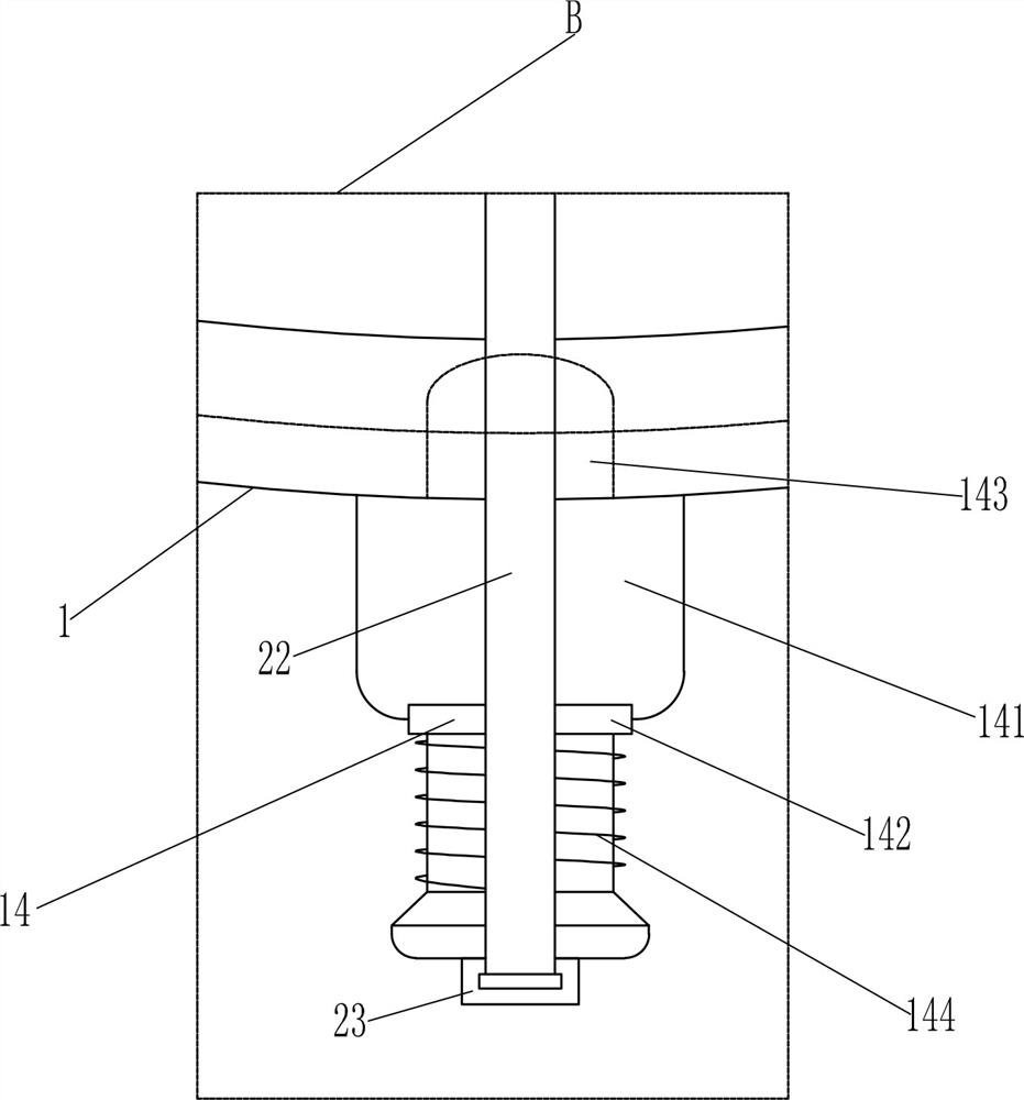
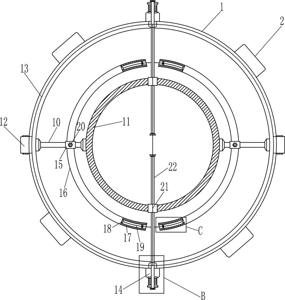
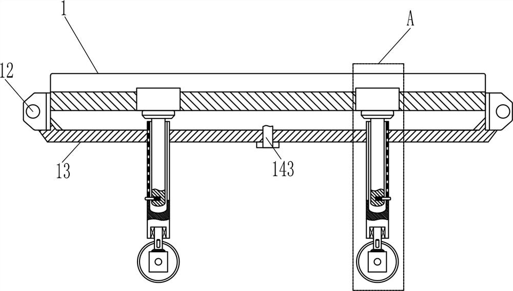
[0024] A park gravel road paving equipment, such as Figure 1-6 As shown, it includes a first ring 1, a mounting block 2, a support rod 3, a first compression spring 5, a circular stop rod 6, a universal wheel 9, a connecting rod 10, a second ring 11, a hinge 12, Fan-shaped baffle plate 13 and fixing device 14, installation blocks 2 are arranged on the left, right, front and rear sides of the first ring 1, the bottom of installation block 2 is connected with support rod 3, and the right and left side support rods 3 are connected to the bottom of right support rod 3 The left side of the lower part is provided with a first groove 4, the inner wall of the first groove 4 is connected with a first compression spring 5, and the outer end of the first compression spring 5 is connected with a circular retaining rod 6, and the circular retaining rod 6 passes through the first Groove 4, the outer side of the support rod 3 is equipped with a grooved rod 7, and the outer side of the groov...
Embodiment 2
[0026] A park gravel road paving equipment, such as Figure 1-6 As shown, it includes a first ring 1, a mounting block 2, a support rod 3, a first compression spring 5, a circular stop rod 6, a universal wheel 9, a connecting rod 10, a second ring 11, a hinge 12, Fan-shaped baffle plate 13 and fixing device 14, installation blocks 2 are arranged on the left, right, front and rear sides of the first ring 1, the bottom of installation block 2 is connected with support rod 3, and the right and left side support rods 3 are connected to the bottom of right support rod 3 The left side of the lower part is provided with a first groove 4, the inner wall of the first groove 4 is connected with a first compression spring 5, and the outer end of the first compression spring 5 is connected with a circular retaining rod 6, and the circular retaining rod 6 passes through the first Groove 4, the outer side of the support rod 3 is equipped with a grooved rod 7, and the outer side of the groov...
Embodiment 3
[0029] A park gravel road paving equipment, such as Figure 1-6As shown, it includes a first ring 1, a mounting block 2, a support rod 3, a first compression spring 5, a circular stop rod 6, a universal wheel 9, a connecting rod 10, a second ring 11, a hinge 12, Fan-shaped baffle plate 13 and fixing device 14, installation blocks 2 are arranged on the left, right, front and rear sides of the first ring 1, the bottom of installation block 2 is connected with support rod 3, and the right and left side support rods 3 are connected to the bottom of right support rod 3 The left side of the lower part is provided with a first groove 4, the inner wall of the first groove 4 is connected with a first compression spring 5, and the outer end of the first compression spring 5 is connected with a circular retaining rod 6, and the circular retaining rod 6 passes through the first Groove 4, the outer side of the support rod 3 is equipped with a grooved rod 7, and the outer side of the groove...
PUM
 Abstract
Description
Claims
Application Information
 - R&D
- Intellectual Property
- Life Sciences
- Materials
- Tech Scout
- Unparalleled Data Quality
- Higher Quality Content
- 60% Fewer Hallucinations
Browse by: Latest US Patents, China's latest patents, Technical Efficacy Thesaurus, Application Domain, Technology Topic, Popular Technical Reports.
© 2025 PatSnap. All rights reserved.Legal|Privacy policy|Modern Slavery Act Transparency Statement|Sitemap|About US| Contact US: help@patsnap.com