Anti-clogging gauze window with humidifying function

An anti-clogging and functional technology, applied in the field of screen windows, can solve the problems of unsmooth air, blocked screen windows, inconvenient daily use, etc., and achieve the effect of improving the purification effect.

Active Publication Date: 2019-04-16
NANJING XUYURUI MATERIAL TECH CO LTD
View PDF5 Cites 4 Cited by
  • Summary
  • Abstract
  • Description
  • Claims
  • Application Information

AI Technical Summary

Problems solved by technology

At present, the structure of the screen window is relatively simple, usually composed of a window frame and a gauze net. After long-term use, the mesh of the gauze net is easy to be blocked, especially in some ore or flour processing plants, the situation of the screen window clogging is more obvious, causing indoor The air is not smooth, and the screen window needs to be cleaned and dredged frequently, which brings inconvenience to daily use

Method used


Image

  • Anti-clogging gauze window with humidifying function
  • Anti-clogging gauze window with humidifying function
  • Anti-clogging gauze window with humidifying function

Examples


Embodiment 1

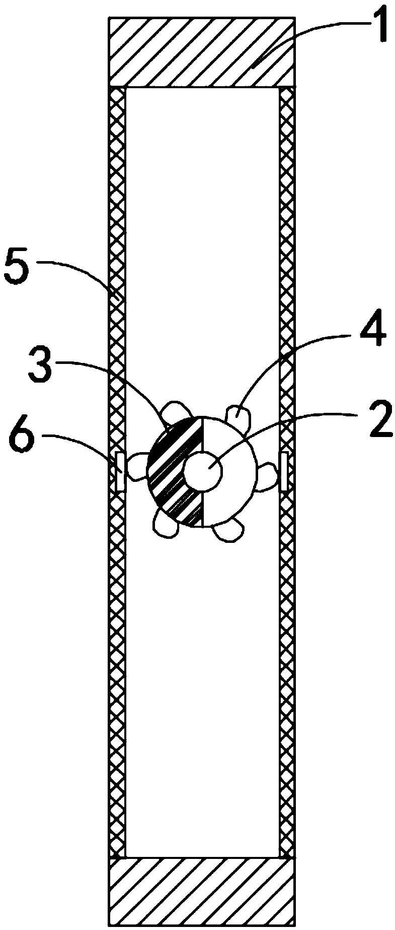
[0019] Such as figure 1 As shown, an anti-clogging screen window with humidification function includes a window frame 1, the inner rotation of the window frame 1 is connected with a horizontally arranged rotating shaft 2, and both ends of the rotating shaft 2 are rotationally connected with the middle part of the window frame 1 through rotating bearings. The rotating shaft 2 is coaxially fixedly connected with a permanent magnet cylinder 3 and two wind-driven wheels 4, and the two wind-driven wheels 4 are located on the left and right sides of the permanent magnet cylinder 3 respectively. 5 is woven with stainless steel wire, the gauze 5 is fixedly connected to the inner side wall of the window frame 1, and the opposite side walls of the two gauzes 5 are fixedly connected with a permanent magnetic strip 6, and the permanent magnetic strip 6 is connected to the permanent magnetic cylinder 3 The positions correspond to each other, the magnetic poles on the opposite sides of the ...

Embodiment 2

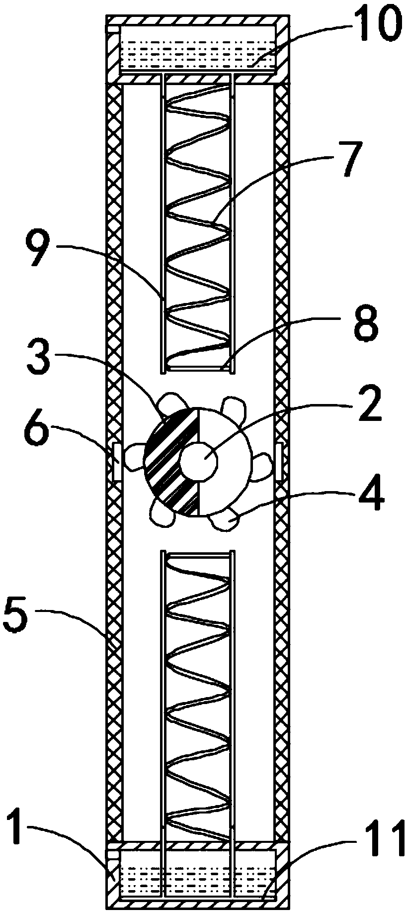
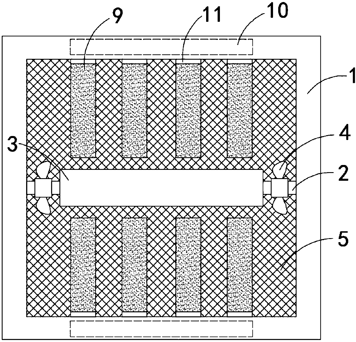
[0022] Such as Figure 2-3 As shown, the difference between this embodiment and Embodiment 1 is that the humidifying mechanism includes a plurality of springs 7 fixedly connected to the side wall of the window frame 1, and one end of the springs 7 close to the permanent magnet cylinder 3 is fixedly connected with a permanent magnet piece 8 It should be noted that the magnetic poles of the permanent magnet piece 8 on the upper side of the rotating shaft 2 and the opposite side of the permanent magnet piece 8 on the lower side of the rotating shaft 2 are the same, and under the action of the permanent magnet cylinder 3, the two springs 7 are always in the opposite direction. state, that is, when one of the springs is in an extended state, the other is in a shortened state, and the spring 7 is fixedly sleeved with a water-absorbing net 9, which can be woven with elastic water-absorbing fibers, and the inside of the window frame 1 A water storage chamber 10 is provided. It should ...


PUM


Abstract

The invention belongs to the field of gauze windows, and particularly relates to an anti-clogging gauze window with a humidifying function. The anti-clogging gauze window comprises a window frame, a horizontal rotary shaft is rotatably connected to the interior of the window frame, a permanent magnetic drum and two pneumatic wheels are coaxially and fixedly connected to the rotary shaft, the two pneumatic wheels are located at the left and right sides of the permanent magnetic drum respectively, and gauze nets are arranged at the front and rear sides of the rotary shaft, and fixedly connectedwith the inner side wall of the window frame; permanent magnetic strips are fixedly connected to the opposite side walls of the two gauze nets, and correspond to the permanent magnetic drum in position, the two opposite sides of the two permanent magnetic strips have the opposite magnetic poles, and humidifying mechanisms are arranged at the upper and lower sides of the rotary shaft. According tothe anti-clogging gauze window, wind power can drive the gauze nets to shake, and the gauze nets can be automatically cleaned; meanwhile, through the arrangement of a spring and a water absorbing sleeve net, air entering a room can be purified and humidified, and the indoor air quality is improved.

Description

technical field [0001] The invention belongs to the field of window screens, in particular to an anti-clogging screen window with humidification function. Background technique [0002] A screen window is a window that functions as insulation and ventilation. At present, the structure of the screen window is relatively simple, usually composed of a window frame and a gauze net. After long-term use, the mesh of the gauze net is easy to be blocked, especially in some ore or flour processing plants, the situation of the screen window clogging is more obvious, causing indoor The air is not smooth, and the screen window needs to be cleaned and dredged frequently, which brings inconvenience to daily use. [0003] For this reason, we propose an anti-clogging screen window with humidification function to solve the above problems. Contents of the invention [0004] The object of the present invention is to solve the above problems and provide a wind-driven anti-clogging screen win...

Claims


Application Information

Patent Timeline
Patent Type & Authority Applications(China)
IPC IPC(8): E06B9/52E06B7/28A47L4/00F03D9/20F24F6/06F24F3/16F24F13/00
CPCA47L4/00E06B7/28E06B9/52F03D9/20F24F3/16F24F6/06F24F13/00Y02E10/72
Inventor 涂玉华
Owner NANJING XUYURUI MATERIAL TECH CO LTD
Why Eureka
Try Eureka