
A high-current low-power consumption detection and acquisition circuit

A technology of acquisition circuit and low power consumption, applied in the field of current detection and acquisition, can solve the problems of reducing and reducing the overcurrent protection point, and achieve the effect of high efficiency, low application prospect and economic benefits

Active Publication Date: 2021-04-02
XIAN MICROELECTRONICS TECH INST
View PDF5 Cites 0 Cited by
  • Summary
  • Abstract
  • Description
  • Claims
  • Application Information

AI Technical Summary

Problems solved by technology

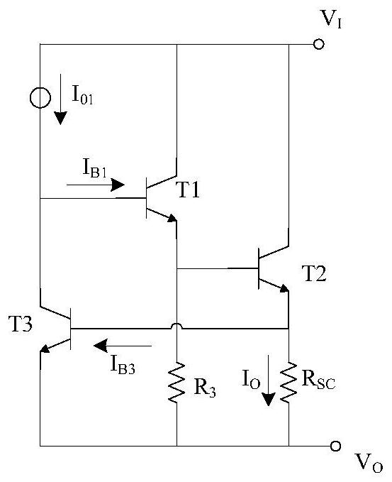
Its disadvantages are: due to V BE3 It is a physical quantity related to temperature, and its value decreases with the increase of temperature, so for the same circuit, with this structure, its overcurrent protection point decreases with the increase of temperature
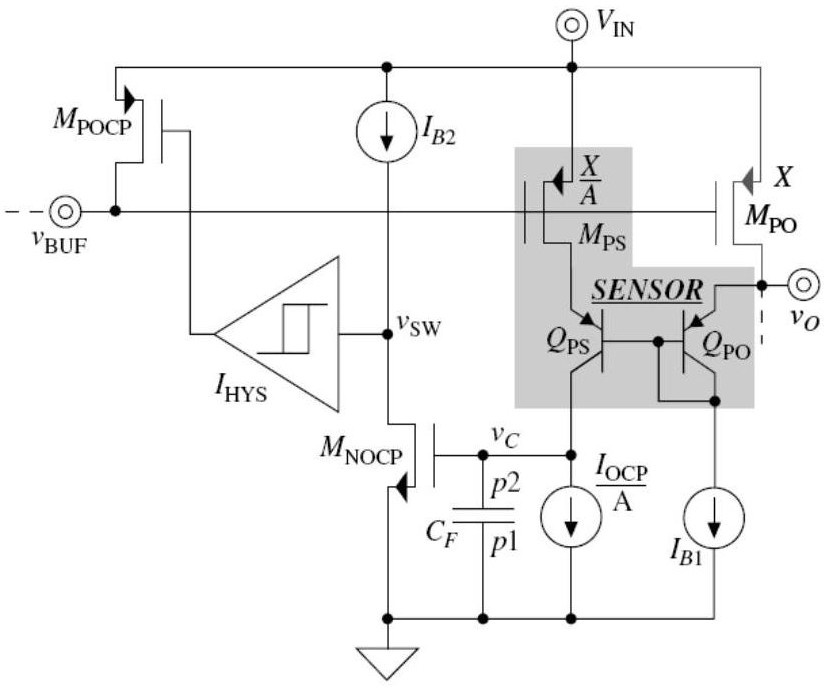
But M PS The current increases with the increase of the output current, and each part of the bias circuit will bring additional power consumption; in addition, the feedback loop of this structure uses a two-stage inverting operational amplifier, and the loop needs to be considered in the design road stability problem

Method used


Image

  • A high-current low-power consumption detection and acquisition circuit
  • A high-current low-power consumption detection and acquisition circuit
  • A high-current low-power consumption detection and acquisition circuit

Examples


Embodiment Construction

[0022] The technical solution of the present invention will be further described below in conjunction with the accompanying drawings and specific embodiments.

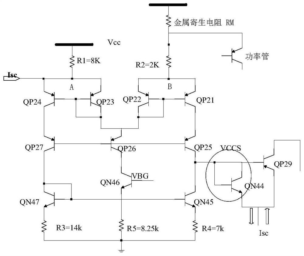
[0023] The present invention provides a detection and acquisition device with high current and low power consumption. The circuit structure of the acquisition device is as follows: image 3 As shown, it includes proportional resistor R1 and resistor R2 connected to the supply voltage, wherein the resistance value of resistor R1 is 8KΩ, and the resistance value of resistor R2 is 2KΩ; resistor R2 is also connected in series with a metal parasitic resistor RM, and the resistance value of metal parasitic resistor RM is 60mΩ, and a power tube is connected between the metal parasitic resistor RM and the resistor R2, and the power tube is a triode, wherein the emitter of the triode is connected between the metal parasitic resistor RM and the resistor R2.

[0024] The resistor R1 and the resistor R2 are respectively connected ...


PUM


Abstract

The invention discloses a high-current low-power-consumption detecting and collecting circuit comprising two proportional resistors R1 and R2 connected with a supply voltage. A resistance ratio of theresistor R1 to the resistor R2 is 4 to 1. The resistor R1 is connected to a first current mirror; and the resistor R2 is connected to a second current mirror. The resistor R2 is also connected with ametal parasitic resistor RM; and a power tube is connected between the RM and the R2. A short circuit Isc is connected to the first current mirror. One end of the first current mirror and one end ofthe second current mirror are connected in series and then are connected in series with two triodes successively, and a resistor R5 is connected. Two triodes are connected in series to the other end of the first current mirror and then are connected with a resistor R3; and the other end of the second current mirror is connected in series with two triodes and then is connected with a resistor R4. With the voltage drop of the metal interconnect parasitic resistor, negative feedback control is formed by fast response to the driving to the power tube by the current comparator, so that the real-time and efficient detection and collection functions are realized.

Description

technical field [0001] The invention belongs to the technical field of current detection and acquisition; in particular, it relates to a detection and acquisition circuit with high current and low power consumption. Background technique [0002] With the development of integrated circuit technology, more and more high-power load power management chips tend to integrate power separation devices into the chip. When the output current is overloaded or even short-circuited, the output power consumption on the power tube will permanently damage the power management chip and the subsequent load device. Therefore, output current and power detection and acquisition technology is an important research direction for power management chips. At present, commonly used current detection technologies include resistance sampling output current detection mode and current mirror sampling output current detection mode. [0003] The resistance sampling output current detection method includes ...

Claims


Application Information

Patent Timeline
Patent Type & Authority Patents(China)
IPC IPC(8): G01R19/00
CPCG01R19/0092
Inventor 武琪
Owner XIAN MICROELECTRONICS TECH INST
Learn More