
A large copper sleeve casting equipment

A technology of casting equipment and copper sleeves, which is applied in the field of large-scale copper sleeve casting equipment, can solve problems such as low production efficiency, uneven density of copper sleeves, unfavorable mass production, etc., and achieve the goal of improving quality, improving convenience, and increasing molding speed Effect

Active Publication Date: 2020-04-24
ZHEJIANG WANZHONG MACHINERY MFG
View PDF12 Cites 0 Cited by
  • Summary
  • Abstract
  • Description
  • Claims
  • Application Information

AI Technical Summary

Problems solved by technology

However, in the existing centrifugal casting equipment, when the liquid copper alloy is poured into the mold, part of it has been cooled and formed into blocks, which makes the density of the formed copper sleeve uneven, and is prone to deformation or cracks due to stress concentration during use.
Moreover, only a single copper sleeve can be cast at a time, and the production efficiency is low, which is not conducive to mass production. Therefore, it is necessary to design a casting equipment for a large copper sleeve

Method used

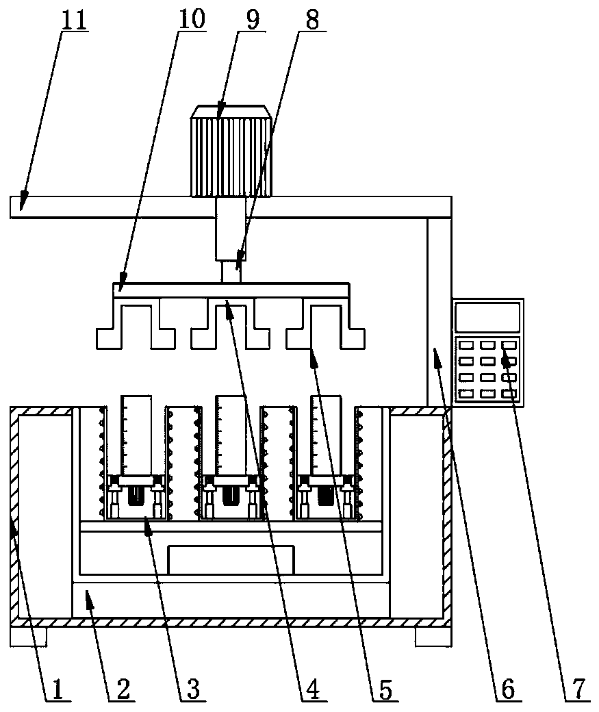

Image

  • A large copper sleeve casting equipment
  • A large copper sleeve casting equipment
  • A large copper sleeve casting equipment

Examples


Embodiment Construction

[0018] The following will clearly and completely describe the technical solutions in the embodiments of the present invention with reference to the accompanying drawings in the embodiments of the present invention. Obviously, the described embodiments are only some, not all, embodiments of the present invention. Based on the embodiments of the present invention, all other embodiments obtained by persons of ordinary skill in the art without making creative efforts belong to the protection scope of the present invention.

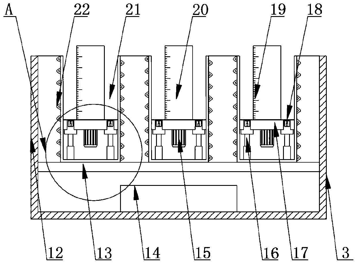
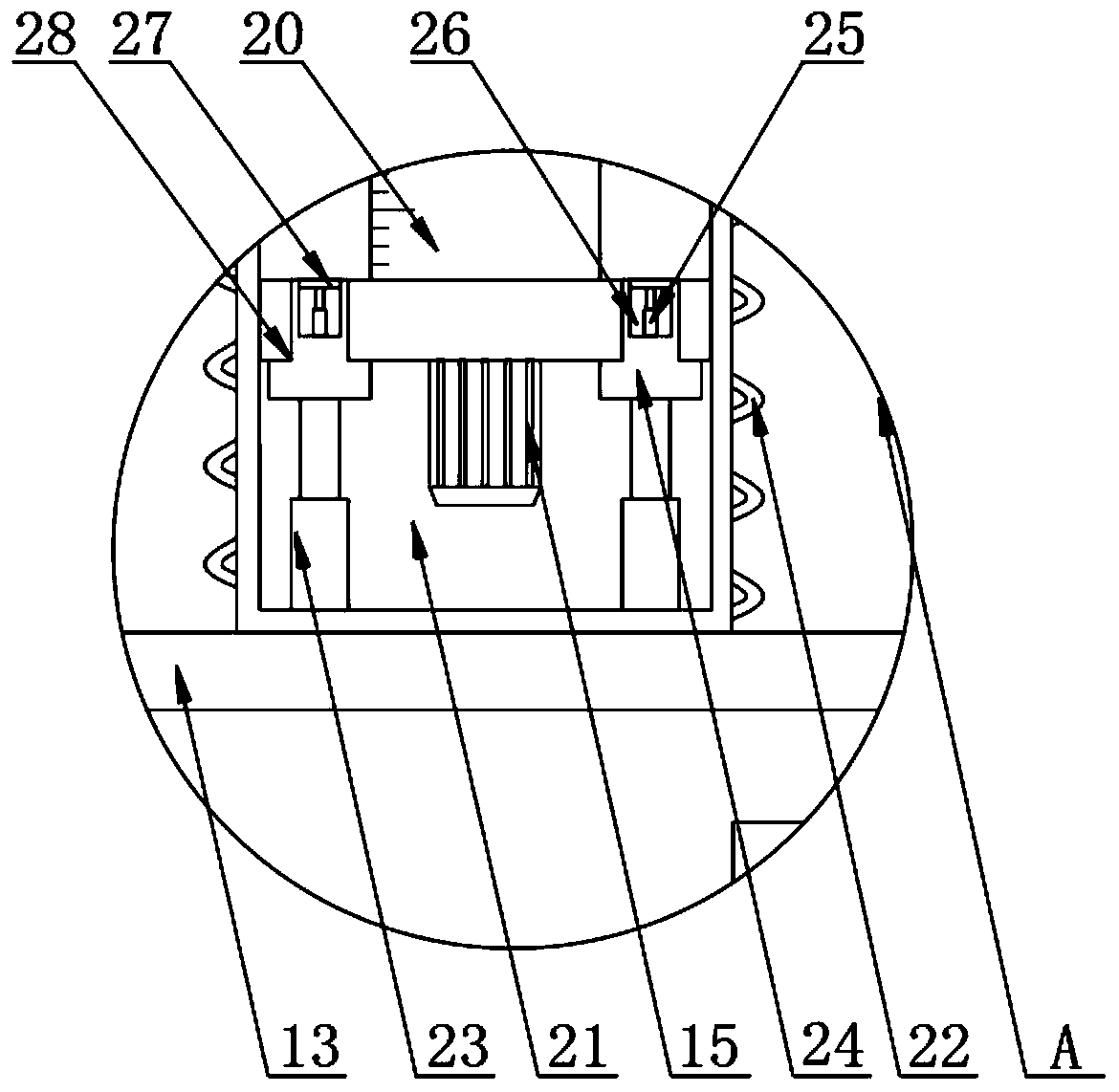
[0019] see Figure 1-4 , the present invention provides a technical solution: a large-scale copper sleeve casting equipment, including a frame 1, a rotating base 2, a forming mechanism 3, a mold cover 4, a fixing groove 5, a pillar 6, a control board 7, a first electric pusher Rod 8, rotating motor 9, fixed plate 10 and suspension beam 11, the bottom inner wall of frame 1 is fixed with rotating base 2 by bolts, the top of rotating base 2 is connected with form...


PUM


Abstract

The invention discloses a casting device for a large copper sleeve. The device comprises a rack, a rotating base, a forming mechanism, a die cover, a fixing groove, a supporting column, a control plate, a first electric pushing rod, a rotating motor, a fixing plate and a suspension beam, wherein the rotating base is fixed to the inner wall of the bottom part of the rack through a first bolt; the forming mechanism is connected to the top part of the rotating base through a bearing; the supporting column is fixed to one side of the top part of the rack by welding; the control plate is fixed to one side of the supporting column through a hoop; the suspension bema is fixed to one side of the top part of the supporting column by welding; the rotating motor is fixed to the center of the top partof the suspension beam through a second bolt; the top part of the first electric pushing rod passes through the center of the bottom part of the suspension beam and is connected to an output shaft ofthe rotating motor; and a fixing plate is fixed to the bottom part of the first electric pushing rod through a third bolt. The device is simple in structure, and convenient to use; the copper sleeveforming speed is effectively increased; and meanwhile, the product quality is effectively improved.

Description

technical field [0001] The invention relates to the technical field of copper sleeve production, in particular to casting equipment for large copper sleeves. Background technique [0002] Copper sleeve is a very broad name. Copper sleeve is a component used in sliding and rotating machinery to reduce friction while transmitting thrust and supporting and fixing. Copper sleeves, also known as "copper bearings", are made of various copper alloys for the lubrication of mechanical parts. They are used in various large and heavy machinery and are important components of machinery. Commonly used materials for copper sleeves include ZCuSn 10 Pb 1 、ZCuSn 10 Pb 5 , ZCuPb 10 sn 10 , ZCuPb 15 sn 8 , ZCuZn 38 mn 2 Pb 2 Wait. Copper sleeves are generally manufactured by metal mold casting, centrifugal casting, sand casting, etc. Among them, centrifugal casting is a casting method in which liquid copper alloy is poured into a rotating mold, filled and solidified into a copper ...

Claims


Application Information

Patent Timeline
Patent Type & Authority Patents(China)
IPC IPC(8): B22D13/04B22D13/10B22D13/12
CPCB22D13/04B22D13/105B22D13/108B22D13/12
Inventor 方灿根
Owner ZHEJIANG WANZHONG MACHINERY MFG
Learn More