
Step-by-step demolding mold

A mold and demolding technology, applied in the field of step-by-step demolding molds, can solve the problems of inconvenient removal of molded parts, inconvenience of mold separation, and burrs of molded parts, so as to prevent mutual sticking, improve safety, and avoid burrs.

Inactive Publication Date: 2021-03-16
盐城市金德模具制造有限公司
View PDF6 Cites 2 Cited by
  • Summary
  • Abstract
  • Description
  • Claims
  • Application Information

AI Technical Summary

Problems solved by technology

[0004] 1. When demoulding the mold, since the fixed mold and the movable mold will stick together after injection molding, it is inconvenient to separate the molds during demoulding;
[0005] 2. At the same time, after the injection molding of the mold and the molded parts is completed, it is inconvenient to take out the molded parts due to the residual temperature of the molded parts, which makes it more troublesome to take out;
[0006] 3. During injection molding, if the seals of the two sets of molds are not tight enough, excess material will flow out from the gap, resulting in burrs on the molded parts and pollution to the molds

Method used


Image

  • Step-by-step demolding mold
  • Step-by-step demolding mold
  • Step-by-step demolding mold

Examples


Embodiment Construction

[0023] The following will clearly and completely describe the technical solutions in the embodiments of the present invention with reference to the accompanying drawings in the embodiments of the present invention. Obviously, the described embodiments are only some of the embodiments of the present invention, not all of them. Based on the embodiments of the present invention, all other embodiments obtained by persons of ordinary skill in the art without making creative efforts belong to the protection scope of the present invention.

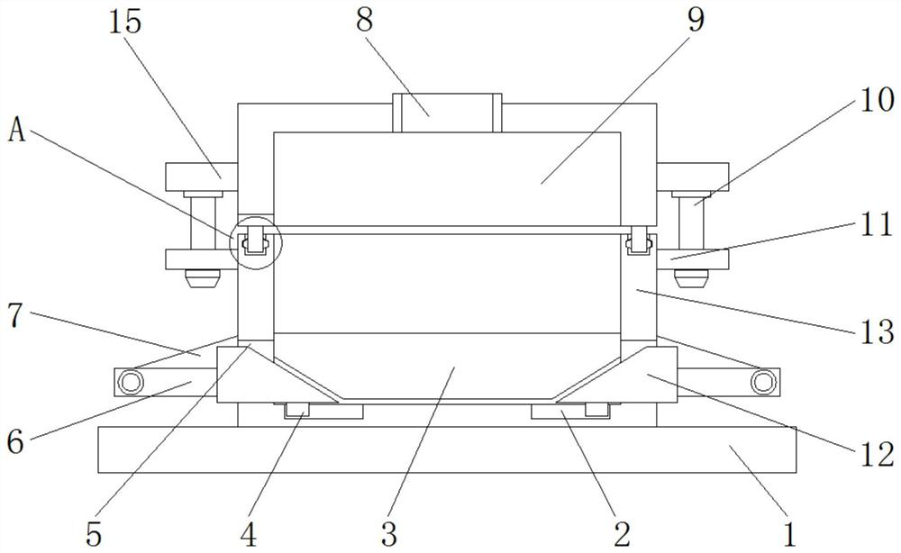
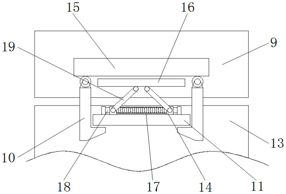
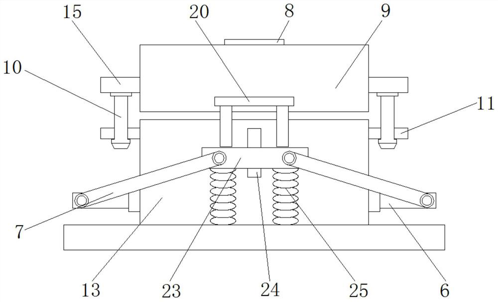
[0024] see Figure 1-4 , the embodiment provided by the present invention: a step-by-step demoulding mold, comprising a base 1 and a movable mold 9, a fixed mold 13 is arranged at the middle position of the top of the base 1, and a first top plate 3 is set inside the fixed mold 13, It is convenient to eject the workpiece;

[0025] The two sides of the bottom of the first top board 3 are inclined, so that the first top board 3 can be lifted up; ...


PUM


Abstract

The step-by-step demolding mold comprises a base and a movable mold body, fixed mold bodies are arranged in the middle of the top of the base, a first ejector plate is arranged in the fixed mold bodyin a sleeved mode, through holes are formed in the bottoms of the two sides of the two fixed mold bodies, and first sliding grooves are symmetrically formed in the two sides of the bottom of the interiors of the fixed mold body; and sliding blocks are slidably arranged in the two sets of first sliding grooves correspondingly, pushing blocks are arranged at the tops of the two sets of sliding blocks correspondingly, and the sides, away from each other, of the two sets of pushing blocks extend out of the fixed mold bodies. According to the step-by-step demolding mold, through mutual cooperationof the first sliding grooves, the first ejector plate, push rods, first hinge rods and second springs, an injection-molded workpiece can be rapidly ejected out under the action of the four sets of second springs, the workpiece can be prevented from making direct contact with the hand of a person at the high temperature, and the safety during demolding is improved.

Description

technical field [0001] The invention relates to the technical field of step-by-step demoulding molds, in particular to a step-by-step demoulding mold. Background technique [0002] Molds are various molds and tools used in industrial production for injection molding, blow molding, extrusion, die-casting or forging forming, smelting, stamping, stretching, etc. to obtain the required products. In short, molds are used to shape objects This tool is composed of various parts, and different molds are composed of different parts. It mainly realizes the processing of the shape of the article through the change of the physical state of the formed material; [0003] But there is certain deficiency in existing mold when using: [0004] 1. When demoulding the mold, since the fixed mold and the movable mold will stick together after injection molding, it is inconvenient to separate the molds during demoulding; [0005] 2. At the same time, after the injection molding of the mold and t...

Claims


Application Information

Patent Timeline
Patent Type & Authority Applications(China)
IPC IPC(8): B29C45/40B29C45/84F16J15/06
CPCB29C45/401B29C45/84F16J15/061
Inventor 陈春进胥忠军帖德礼
Owner 盐城市金德模具制造有限公司
Learn More