Upsetting forging press and operating method

A working method and technology of an upsetting machine, which are applied to the upsetting machine and the work field, can solve the problems of inflexibility, inconvenient stroke adjustment, and small space for upsetting of a high-speed forging machine, so as to reduce the technical quality requirements, easy to operate and Faster, lower productivity costs

Active Publication Date: 2016-04-06
西大(常熟)研究院有限公司
View PDF8 Cites 1 Cited by
  • Summary
  • Abstract
  • Description
  • Claims
  • Application Information

AI Technical Summary

Problems solved by technology

However, the forging machine belongs to the die rotating equipment, therefore, the same blank needs to be forged multiple times in the same die, and even the final completion does not leave a die
However, the upsetting deformation of the same die is limited, so the quality of upsetting is not good, and the ejection is also difficult.
In addition, the upsetting space of the high-speed forging molding machine with this structure is small, which is not convenient for feeding, upsetting and discharging operations.
[0007] In addition, when upsetting the billet, due to the different size requirements of the formed parts, the ejection mechanism needs to adjust its movement stroke according to the requirements of the formed parts. However, the adjustment of the ejection mechanism in the existing upset forging machine is set On the machine body, that is, the adjustment mechanism of the ejector mechanism is located outside the main mold, and the ejection stroke must be adjusted under the premise that the upset forging machine stops working. Therefore, not only the ejection stroke cannot be adjusted flexibly, but also the upsetting forging will be affected. At the same time, it is very inconvenient to adjust the stroke of the ejector
In addition, most of the ejection mechanisms are now mechanical structures. As mentioned above, the length requirements of the formed parts for the upsetting blank are different, so the stroke of the ejection mechanism needs to be adjusted frequently; at the same time, when the upsetting forging After the machine has been working for a period of time, due to the wear of the ejector mechanism, in order to ensure the quality of the formed parts, it is also necessary to adjust the stroke of the ejector mechanism; but no matter what the above situation is, the adjustment of the mechanical ejector mechanism is very troublesome ,not flexible
[0008] For the existing upsetting machines, the dies are all fixed on the machine body. When it is necessary to replace or adjust the dies, the upsetting machine must be stopped before it can be carried out, which also affects the working efficiency of the upsetting machine. , it is also inconvenient to replace and adjust the die

Method used


Image

  • Upsetting forging press and operating method
  • Upsetting forging press and operating method
  • Upsetting forging press and operating method

Examples


Embodiment 1

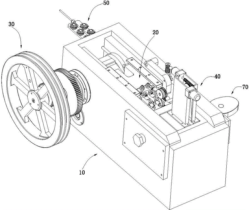
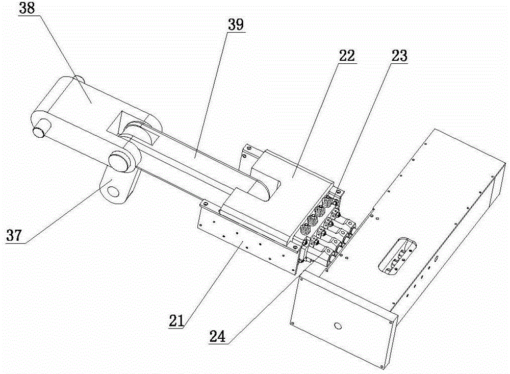
[0079] Such as figure 1 and figure 2 As shown, the upset forging machine includes a body 10, a punch assembly 20 installed on the body 10, a punch assembly driving mechanism 30 for driving the punch assembly 20, an ejector mechanism 40, a feeding mechanism 50 arranged on the body 10, The main mold assembly 60 and the main mold driving mechanism 70 driving the translation of the main mold assembly 60 .

[0080] Such as image 3 and Figure 4 As shown, the described body 10 includes a frame 11, a seat body 12 and a cover plate 13; the frame 11 includes a frame body 111 and a frame seat 112 corresponding to the main mold assembly 60, as Figure 4 As shown, the frame seat 112 includes a frame body 1122 and an end plate 1123, the frame body 1122 has a housing cavity 1121, one end of the housing cavity 1121 has an opening 11211, and the end plate 1123 is fixed on the On the base body 1122 . In this embodiment, the two ends of the frame seat 112 and the seat body 12 protrude fr...

Embodiment 2

[0120] Such as Figure 33 and Figure 34 As shown, the upset forging machine includes a body 10, a punch assembly 20 installed on the body 10, a punch assembly driving mechanism 30 for driving the punch assembly 20, an ejector mechanism 40, a feeding mechanism 50 arranged on the body 10, The main mold assembly 60 and the main mold driving mechanism 70 driving the translation of the main mold assembly 60 .

[0121] Such as image 3 and Figure 4 As shown, the described body 10 includes a frame 11, a seat body 12 and a cover plate 13; the frame 11 includes a frame body 111 and a frame seat 112 corresponding to the main mold assembly 60, as Figure 4 As shown, the frame seat 112 includes a frame body 1122 and an end plate 1123, the frame body 1122 has a housing cavity 1121, one end of the housing cavity 1121 has an opening 11211, and the end plate 1123 is fixed on the On the base body 1122 . In this embodiment, the two ends of the frame seat 112 and the seat body 12 protrude...


PUM


Abstract

The invention discloses an upsetting forging press and an operating method. Material ejection servo motors are adopted for driving a material ejection mechanism of the upsetting forging press, and the material ejection mechanism is installed in an integral main die assembly. The integral main die assembly comprises a main die base. A material shearing die installation hole and an upsetting female die installation hole are formed in the main die base. The operating method comprises the steps that feeding is conducted, and displacement all-round material shearing is achieved through horizontal movement of the integral main die assembly; and then upsetting is conducted, and blanks or formed members are ejected out through the material ejection mechanism. According to the operating method, an independent material shearing mechanism is omitted and meanwhile parts in the integral main die assembly can be replaced and adjusted outside a machine body, so that the upsetting efficiency is improved, and the stroke and position of the material ejection mechanism can be adjusted conveniently and flexibly.

Description

technical field [0001] The invention relates to a heading machine and a working method of the heading machine. Background technique [0002] The upsetting machine is a device that uses the back and forth movement of the large slider to upset the blank in the main die through the punch. [0003] Upsetting machine is mainly composed of machine body, punch assembly, punch assembly driving mechanism, main mold, ejector mechanism, feeding mechanism and shearing mechanism. [0004] In the traditional upsetting machine, the punch assembly and the die included in the main die are all fixed on the corresponding machine body. The upsetting machine with this structure has many mechanical mechanisms, complex structure, many faults, difficult operation and low upsetting efficiency. , Feeding and discharging are more troublesome. [0005] At present, the one-die two-blow upsetting machine and the multi-die multi-punch upsetting machine are used more frequently to realize the displacemen...

Claims


Application Information

Patent Timeline
Patent Type & Authority Applications(China)
IPC IPC(8): B21F5/00B21F11/00
Inventor 杨东佐
Owner 西大(常熟)研究院有限公司
Why Eureka
Try Eureka