Plastic injection mold and injection molding method

An injection mold and plastic technology, applied in the direction of coating, can solve the problems of reduced stability, slow ejection speed, injection molding failure, etc., to achieve the effect of improving production efficiency, improving molding quality, and improving stability

Pending Publication Date: 2022-05-27
徐海华
View PDF0 Cites 2 Cited by
  • Summary
  • Abstract
  • Description
  • Claims
  • Application Information

AI Technical Summary

Problems solved by technology

[0003] When the current injection mold is in use, the upper mold and the lower mold are pushed by the driving mechanism to close the mold. The mold clamping process mainly engages the clamping column of the upper mold and the clamping groove of the lower mold to fix the upper mold and the lower mold. Hold, so that the injection molding cavity is formed, but the existing clamps and clamp grooves are simply designed to be cylindrical and the wear of the clamps during long-term use reduces the mold clamping time between the upper mold and the lower mold. In the injection molding process, the upper mold and the lower mold become loose, resulting in injection molding failure, and the scrap rate increases; and the existing ejector pin has a complex structure and slow ejection speed, which makes the demoulding efficiency of the mold low

Method used


Image

  • Plastic injection mold and injection molding method
  • Plastic injection mold and injection molding method
  • Plastic injection mold and injection molding method

Examples


Embodiment

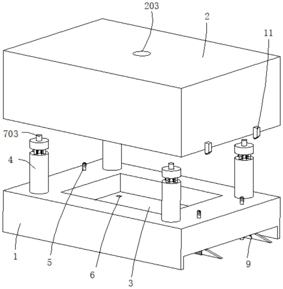
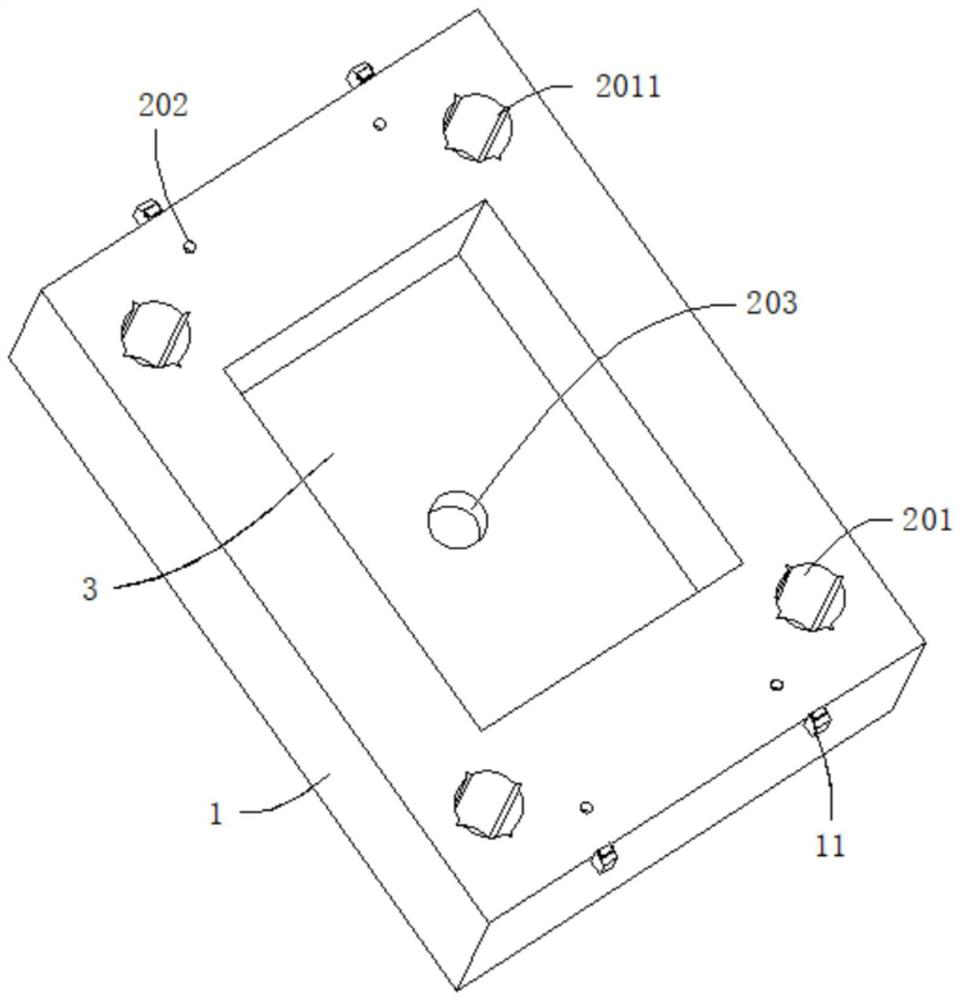
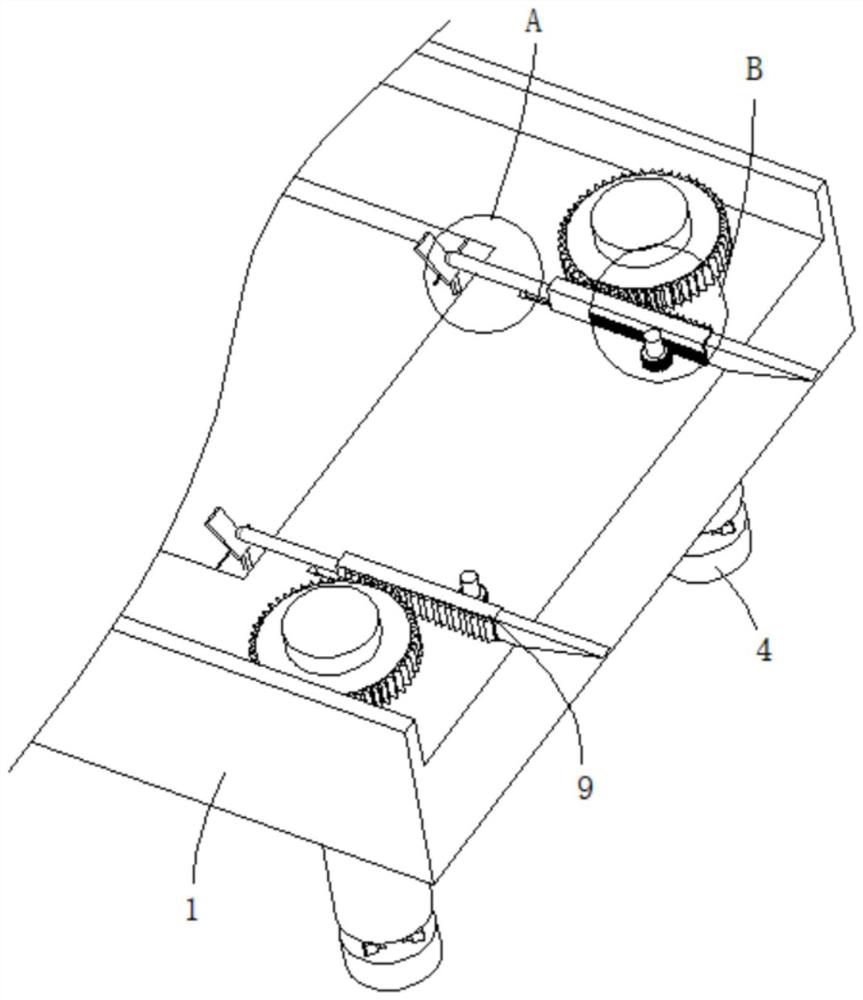
[0041] refer to figure 1 , figure 2 , image 3 and Figure 4 , a plastic injection mold, comprising a lower mold seat 1 and an upper mold seat 2 matched with the lower mold seat 1, characterized in that the lower mold seat 1 and the upper mold seat 2 are both provided with a mold cavity 3, two mold cavities 3. A molding cavity for the injection mold is formed. The upper mold base 2 is provided with a first slot 201 and a second slot 202. The upper mold base 2 is also provided with an injection port 203. The first clamping column 4 and the second clamping column 5 are matched with the first clamping slot 201 and the second clamping slot 202. The first clamping column 4 is provided with an anti-loose mechanism, and the anti-loose mechanism includes an expansion support assembly and an anti-loose assembly. An ejector rod 6 is movably connected in the lower die base 1 , and an ejector mechanism for driving the ejector rod 6 to work is arranged on the lower die base 1 , and the...


PUM


Abstract

The invention discloses a plastic injection mold and an injection molding method, and belongs to the technical field of injection molds. A plastic injection mold comprises a lower mold base and an upper mold base matched with the lower mold base, the lower mold base and the upper mold base are each provided with a mold cavity, the two mold cavities form a forming cavity used for the injection mold, the upper mold base is provided with a first clamping groove and a second clamping groove, and the upper mold base is further provided with an injection molding opening. A first clamping column and a second clamping column which are matched with the first clamping groove and the second clamping groove correspondingly are arranged on the lower die base, and an anti-loosening mechanism is arranged on the first clamping column and comprises an expanding and supporting assembly and an anti-loosening assembly. According to the injection mold, the stability between the upper mold base and the lower mold base is improved, it is guaranteed that the upper mold base and the lower mold base cannot loosen in the injection molding process, then normal operation of the injection molding process is guaranteed, the forming quality of injection molding products is improved, in the demolding process, the injection molding products can be rapidly ejected out through the ejector rod, and the production efficiency of the injection molding products is improved.

Description

technical field [0001] The present invention relates to the technical field of injection moulds, in particular to a plastic injection mould and an injection moulding method. Background technique [0002] The injection mold is a conventional processing equipment for producing plastic products. It mainly includes the main template and the auxiliary template. The upper mold and the lower mold are respectively fixed on the main template and the auxiliary template, and the main template and the auxiliary template are fixed on the injection molding machine. The injection port corresponds to the injection head of the injection molding machine. The injection molding machine realizes the opening and closing of the upper mold and the lower mold through the movement of the internal frame, and the surfaces in contact with the upper mold and the lower mold are the upper parting surface and the lower parting surface respectively. , an upper molding cavity is set on the upper parting surfa...

Claims


Application Information

Patent Timeline
Patent Type & Authority Applications(China)
IPC IPC(8): B29C45/66B29C45/40B29C45/26B29C45/00
CPCB29C45/66B29C45/4005B29C45/2602B29C45/2606B29C45/00B29C2045/664B29C2045/668
Inventor 徐海华
Owner 徐海华
Why Eureka
Try Eureka