A high-voltage inverter multi-IGBT clock synchronous driving method and system

A high-voltage frequency converter, clock synchronization technology, applied in the output power conversion device, electrical components and other directions, can solve the problem that the function index cannot achieve the expected effect, the IGBT drive pulse is not synchronized, the local clock is not synchronized, etc., to avoid failures. Potentially risky, easy-to-achieve, simple-structured effects

Active Publication Date: 2020-08-14
DAYU ELECTRIC
View PDF5 Cites 0 Cited by
  • Summary
  • Abstract
  • Description
  • Claims
  • Application Information

AI Technical Summary

Problems solved by technology

This transmission method is simple to implement, but there may be abnormal continuous 0 or continuous 1 phenomena in the decoded data at the group end, or because the local clocks of each group are not synchronized, the decoded IGBT drive pulses are not synchronized, resulting in system failure. Some functional indicators can not achieve the expected results

Method used


Image

  • A high-voltage inverter multi-IGBT clock synchronous driving method and system
  • A high-voltage inverter multi-IGBT clock synchronous driving method and system
  • A high-voltage inverter multi-IGBT clock synchronous driving method and system

Examples


Embodiment Construction

[0048] The present invention will be described in further detail below in conjunction with the accompanying drawings and embodiments.

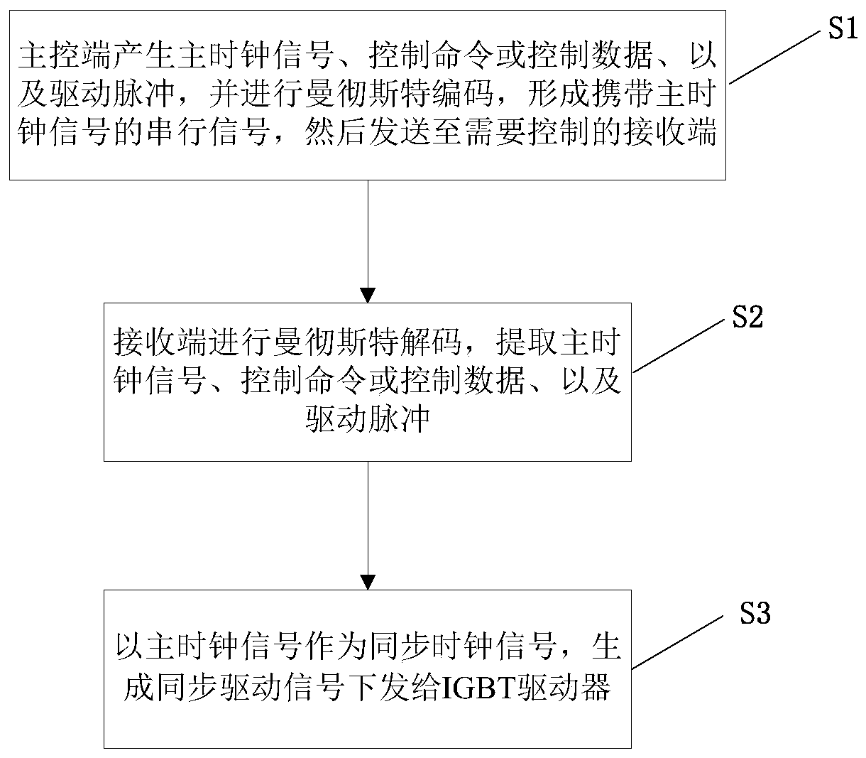
[0049] see figure 1 As shown, the embodiment of the present invention provides a high-voltage inverter multi-IGBT clock synchronous driving method, which includes the steps:

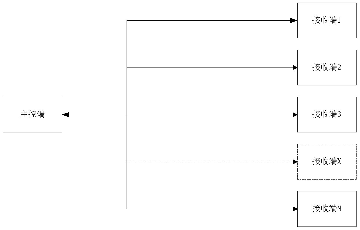
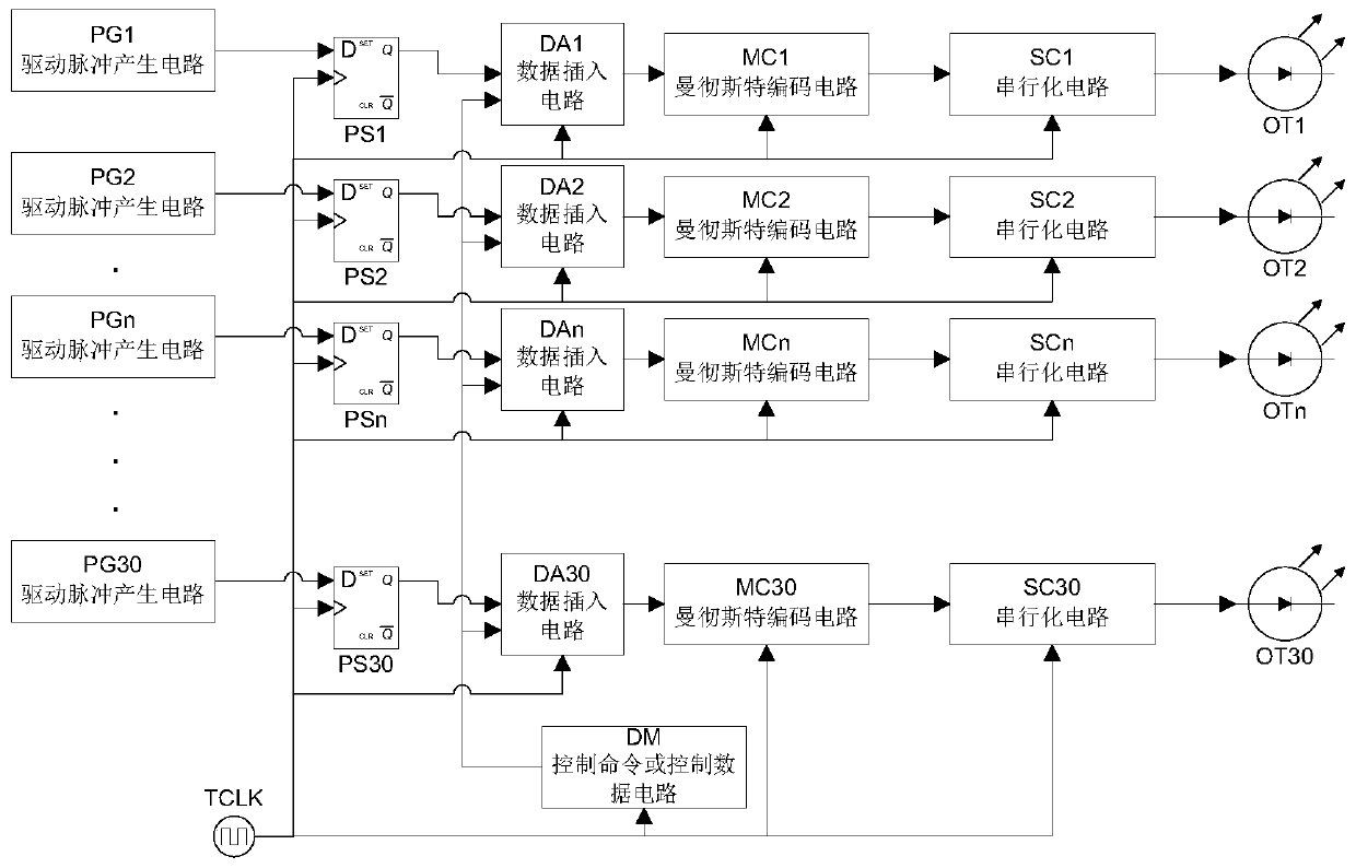
[0050] S1. The main control terminal generates the main clock signal, control command or control data, and driving pulse, and performs Manchester encoding to form a serial signal carrying the main clock signal, and then sends it to the receiving end that needs to be controlled; the control command or control data carries The address code of the above receiving end.

[0051] S2. The receiving end performs Manchester decoding to extract the main clock signal, control command or control data, and driving pulse.

[0052] S3. Using the main clock signal as a synchronous clock signal, generating a synchronous driving signal and sending it to the IGBT driver.

[0053] In thi...


PUM


Abstract

The invention discloses a multi-IGBT clock synchronous driving method and system for a high-voltage frequency converter, and relates to the technical field of electronic device control. The method comprises the steps that a main control end generates a main clock signal, a control command or control data and a driving pulse, performs Manchester encoding to form a serial signal carrying the main clock signal, and sends the serial signal to a receiving end to be controlled, wherein the control command or the control data carries an address code of the receiving end; the receiving end performs Manchester decoding, and extracts the main clock signal, the control command or control data and the driving pulse; the main clock signal is taken as a synchronous clock signal, a synchronous driving signal is generated and transmitted to an IGBT driver. According to the invention, the Manchester codes carry the main clock signal, and the synchronous clock can be recovered through the decoding of the receiving end, so the method and system achieve the synchronous driving of the IGBTs, and have the good anti-jamming capability.

Description

technical field [0001] The invention relates to the technical field of electronic device control, in particular to a multi-IGBT clock synchronous drive method and system for a high-voltage frequency converter. Background technique [0002] In large-scale industrial systems, the application of high-voltage frequency converters is becoming more and more extensive, and the capacity is getting larger and larger. Therefore, the performance requirements for high-voltage frequency converters are also getting higher and higher. There are multiple IGBTs (Insulated Gate Bipolar Transistor, Insulated Gate Bipolar Transistor) inside the high-voltage inverter, and the use of optical fibers to transmit the driving pulse signals of the IGBTs can reduce the difficulty of wiring. [0003] The multiple IGBTs inside the high-voltage inverter are arranged in groups, each group has multiple IGBTs, and the driving signals of each IGBT are different. In order to reduce the number of optical fibers...

Claims


Application Information

Patent Timeline
Patent Type & Authority Patents(China)
IPC IPC(8): H02M1/088
CPCH02M1/088
Inventor 毛康宇何川川陈志国肖少兵袁宁童志刚
Owner DAYU ELECTRIC
Why Eureka
Try Eureka