
Sensor components and sensor systems

A sensor component and sensor technology, applied in the sensor field, can solve the problems of the sensor being unable to work, the switching process is complicated, etc., to achieve the effect of easy system application requirements, meet system application requirements, and save cable costs

Active Publication Date: 2022-05-06
朱佳辉
View PDF8 Cites 0 Cited by
  • Summary
  • Abstract
  • Description
  • Claims
  • Application Information

AI Technical Summary

Problems solved by technology

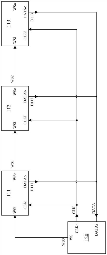
[0005] However, in the above-mentioned sensor system, once a certain sensor does not work, the sensors connected in series after its frame output terminal WSo cannot work. When it is necessary to switch the time period for multiple sensors to transmit data, it is necessary to change multiple sensors and the host computer. The wiring method of 120 needs to reset the parameters in the upper computer 120, and the switching process is more complicated

Method used


Image

  • Sensor components and sensor systems
  • Sensor components and sensor systems
  • Sensor components and sensor systems

Examples


Embodiment Construction

[0027] Hereinafter, the present invention will be described in more detail with reference to the accompanying drawings. In the various figures, identical elements are indicated with similar reference numerals. For the sake of clarity, various parts in the drawings have not been drawn to scale. Also, some well-known parts may not be shown in the drawings.

[0028] In the following, many specific details of the present invention are described, such as device structures, materials, dimensions, processing techniques and techniques, for a clearer understanding of the present invention. However, the invention may be practiced without these specific details, as will be understood by those skilled in the art.

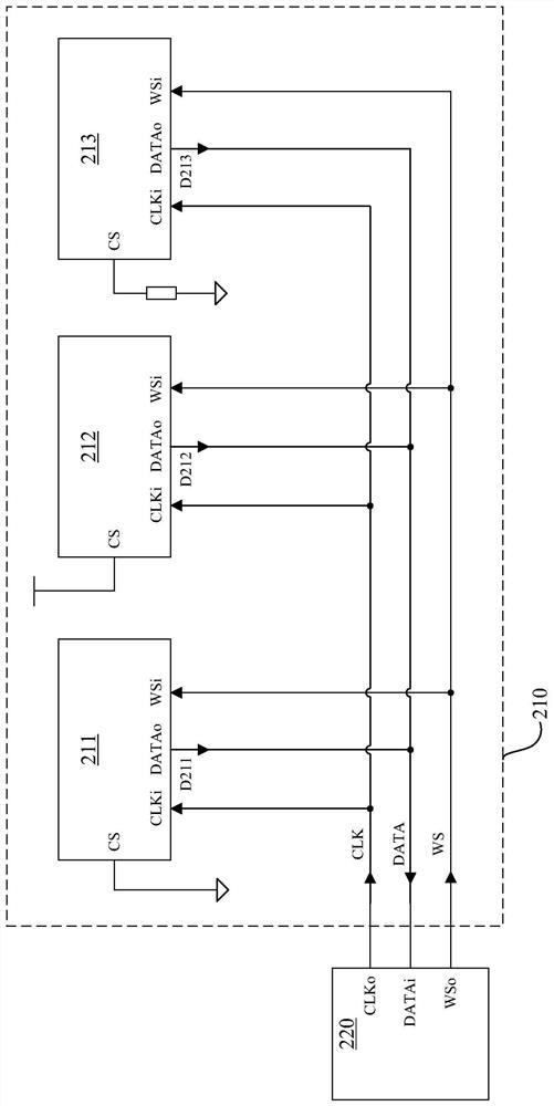
[0029] figure 2 A schematic diagram of a sensor system according to an embodiment of the invention is shown. The system includes: a host computer 220 and a sensor component 210, wherein the sensor component 210 includes a plurality of sensors and a transmission terminal, a...


PUM


Abstract

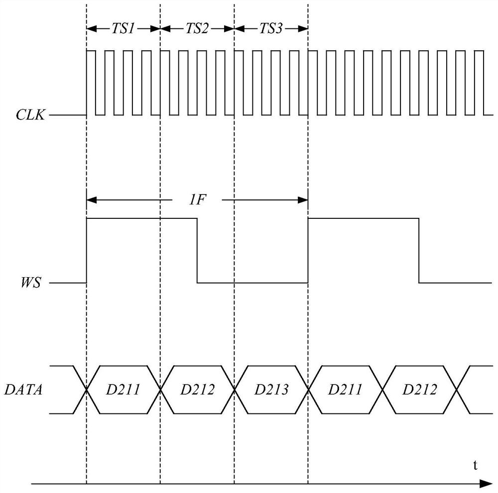
The invention discloses a sensor assembly and a sensor system, wherein the sensor assembly includes a transmission end; and a plurality of sensors, wherein the plurality of sensors are connected to the transmission end via a common data line, and are transmitted from the transmission end through time division multiplexing. The transmission terminals transmit respective data, and the plurality of sensors respectively include chip selection terminals, and the chip selection terminals are connected to different chip selection voltages to be set as predetermined addresses. Each sensor transmits data within a predetermined period of time according to its own predetermined address. When it is necessary to switch the time periods for multiple sensors to transmit data, it is only necessary to switch the chip select voltage connected to the chip select terminal of the corresponding sensor, or only need to set the upper computer, so that it is necessary to change multiple sensors than in the prior art It is faster and more convenient to re-set the parameters of the upper computer for the wiring and switch, and it is easier to meet the flexible system application requirements.

Description

technical field [0001] The invention belongs to the technical field of sensors, and more specifically relates to a sensor component and a sensor system. Background technique [0002] Time Division Multiplexing (TDM) refers to dividing the transmission time of the signal in the communication system between the sensor and the upper computer. The entire transmission time is divided into multiple time intervals, and each time interval is occupied by one signal. The signals are transmitted in different time intervals, and a circuit transmits multiple signals by sending a part of each signal across time. [0003] figure 1 A sensor system in the prior art is shown, in which a plurality of sensors 111 to 113 send data DATA to an upper computer 120 in a TDM manner. The host computer 120 includes a clock output terminal CLKo for providing a clock signal CLK, a frame output terminal WS for providing a frame signal WS0, and a data input terminal DATAi for receiving data DATA. Each of...

Claims


Application Information

Patent Timeline
Patent Type & Authority Patents(China)
IPC IPC(8): H04J3/02H04J3/16
CPCH04J3/02H04J3/16
Inventor 朱佳辉
Owner 朱佳辉
Learn More