Assembly device for stacking a fuel cell stack

A fuel cell stack and assembly device technology, applied in the direction of fuel cells, circuits, electrical components, etc.

Pending Publication Date: 2019-04-16
THYSSENKRUPP SYST ENG +1
View PDF13 Cites 0 Cited by
  • Summary
  • Abstract
  • Description
  • Claims
  • Application Information

AI Technical Summary

Problems solved by technology

This situation is made worse by the fact that the upper and lower cover plates protrude laterally beyond the fuel cell, making it necessary to take specific structural precautions to provide the fuel cell layers with a lateral locating surface unobstructed by the cover plates

Method used


Image

  • Assembly device for stacking a fuel cell stack
  • Assembly device for stacking a fuel cell stack
  • Assembly device for stacking a fuel cell stack

Examples


Embodiment Construction

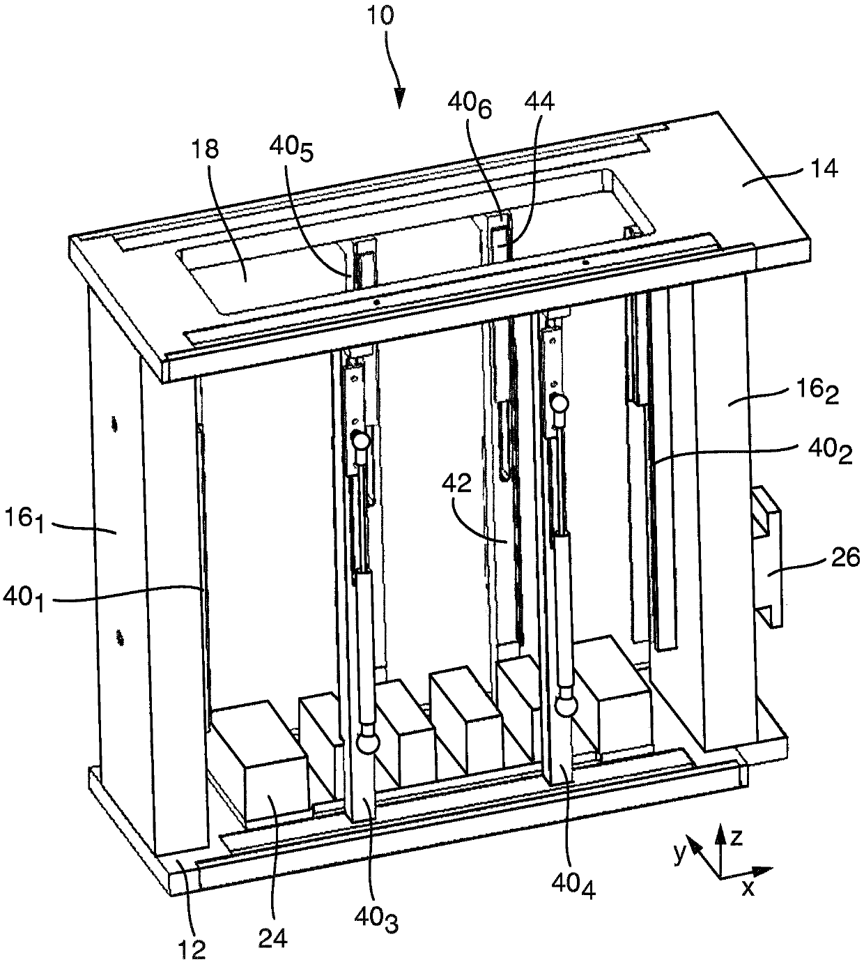
[0024] figure 1 An assembly device 10 according to the invention is shown, which depicts an assembly aid for producing a fuel cell stack. The assembly device 10 consists of a base plate 12, a cover plate 14, and connecting pieces 16 extending on both sides between the base plate 12 and the cover plate 14 1 and 16 2 . The base plate 12 includes a component housing portion 24 housing a fuel cell stack to be stacked. The component receiving portion 24 is vertically adjustable in the height direction within the assembly device 10 . Connector 16 1 、16 2 At least one of them may comprise a contact plate 26 via which the assembly device 10 may be held and moved by a manipulator (not shown, eg a robot). To describe the direction, in figure 1 A rectangular coordinate system is shown in , which has an x-direction, a y-direction, and a z-direction. Based on this, the z direction represents the vertical direction, and the x and y directions represent the horizontal direction.

[...


PUM


Abstract

The invention relates to an assembly device for stacking a fuel cell stack in a vertical direction, said fuel cell stack being structured of membrane electrode units and bi-polar plates in alternation.

Description

technical field [0001] The invention relates to an assembly device for vertically stacking a fuel cell stack consisting of alternating membrane electrode units and bipolar plates. Background technique [0002] A fuel cell stack or "stack" simply consists of a plurality of fuel cells stacked one on top of the other, an upper cover and a lower cover. Membrane electrode units (or MEA for short) and bipolar plates (or BPP for short) are alternately stacked between the upper cover plate and the lower cover plate. The number of stacked fuel cells depends on the desired power output of the "stack" and may be about 600 components with a construction height of about 680 mm. Devices for assembling fuel cell stacks are disclosed, for example, in DE 10 2016 213 266 A1 and DE 10 2015 223 193 A1. [0003] Fuel cell stacks can conventionally be produced using two different processes. Thus, on the one hand, stacking, pressing and final tensioning element assembly can be performed in the ...

Claims


Application Information

Patent Timeline
IPC IPC(8): H01M8/2404
CPCH01M8/2404H01M8/1004H01M8/2465
Inventor 安德里亚斯·沃尔特
Owner THYSSENKRUPP SYST ENG
Why Eureka
Try Eureka