Eureka AIR delivers breakthrough ideas for toughest innovation challenges, trusted by R&D personnel around the world.

Winding device of drawbench

A technology of winding device and wire drawing machine, which is applied in the field of wire drawing machine, can solve problems such as easy to be broken, finished wire broken, wire broken, etc., to achieve the effect of preventing being broken, ensuring continuity and improving winding quality

Active Publication Date: 2019-04-19
GUIZHOU AEROSPACE NANHAI SCI & TECH
View PDF5 Cites 2 Cited by
  • Summary
  • Abstract
  • Description
  • Claims
  • Application Information

AI Technical Summary

Problems solved by technology

Because the wire drawing speed of the wire drawing machine is very fast, and the obtained wire is very thin, usually with a diameter below 0.1 mm, if the winding drum (8) does not take back the finished wire well during wire collection, it is easy to cause the wire to be drawn. Pulling off, especially when the reel (8) is rewinding at a constant speed, with the continuous increase of the outer diameter of the reel, the probability of breaking the finished thread increases greatly. In the prior art, it is generally through tension The position information of the pendulum is fed back to the corresponding control system, and the winding speed of the winding drum is adjusted through the control system. However, when this method is adjusted, only the rotating speed of the winding drum is adjusted, and the speed of the winding drum is not adjusted. The relative position between the wire drawing machine and the wire drawing machine is adjusted, and the finished wire drawing is still in a bent state in some local areas, which is easy to be broken

Method used


Image

  • Winding device of drawbench
  • Winding device of drawbench
  • Winding device of drawbench

Examples


Embodiment Construction

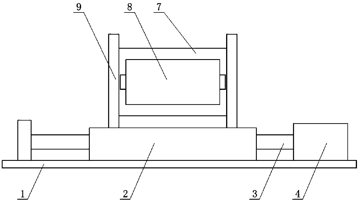
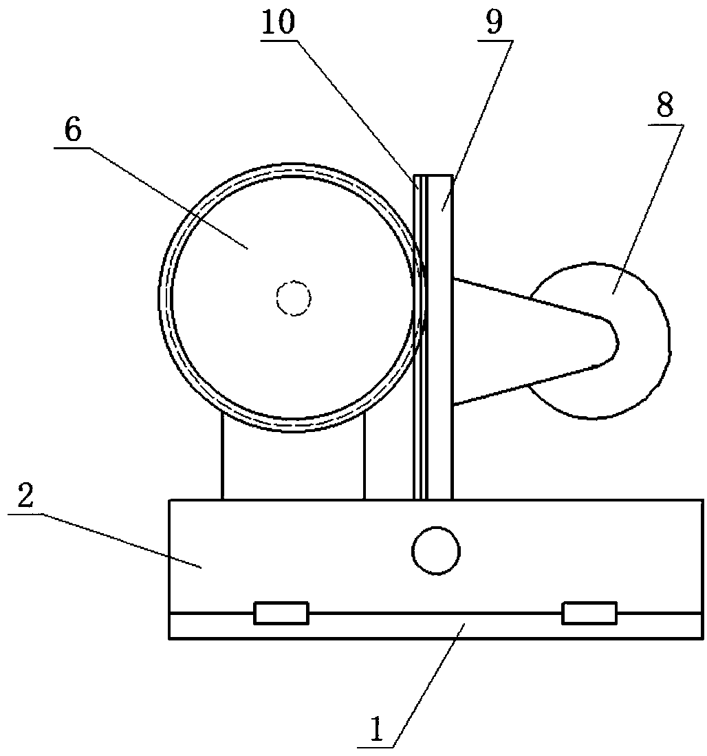
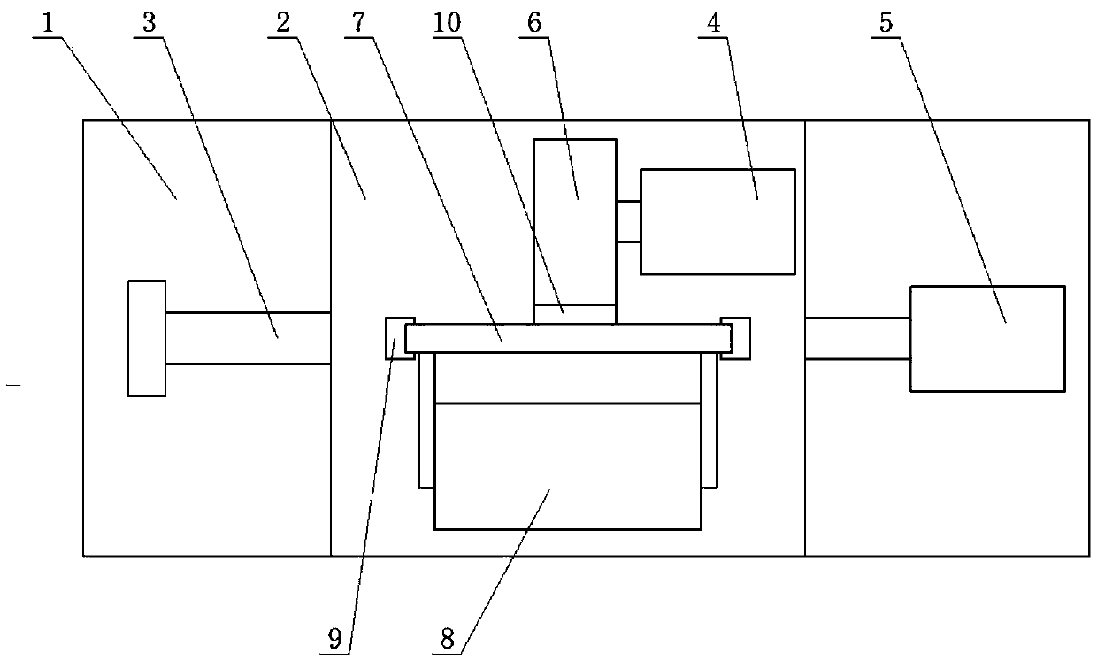
[0017] The technical solution of the present invention is further described below, but the scope of protection is not limited to the description.

[0018] Such as figure 1 , figure 2 , image 3 As shown, the present invention provides a wire drawing machine rewinding device, including a base plate 1, a workbench 2, a ball screw 3, a drive motor A4, a drive motor B5, a gear 6, a vertical plate 7 and a reel 8, and the ball screw 3 Both ends are installed on the base plate 1 through the bearing seat, the drive motor A4 is fixedly installed on the base plate 1, the workbench 2 is set on the ball screw 3, the end of the ball screw 3 is connected with the output shaft of the drive motor A4, and the drive motor B5 is installed on the workbench 2, and a pair of pillars 9 are erected on the workbench 2, and the rails arranged along the vertical direction are arranged on the pillars 9. The two ends of the tube 8 are installed on the front side of the vertical plate 7 through the bea...


PUM

PropertyMeasurementUnit
lengthaaaaaaaaaa

Abstract

The invention provides a winding device of a drawbench. The winding device of the drawbench comprises a bottom plate, a workbench and a vertical plate. A ball screw and a drive motor A are mounted onthe bottom plate. The workbench is mounted on the ball screw in a sleeving manner. The ball screw is connected with an output shaft of the drive motor A. A drive motor B and supporting columns are mounted on the workbench. A rail arranged in the vertical direction is arranged on the supporting columns. The left end and the right end of the vertical plate are sleeved in the rail. A winding barrel is mounted on the front side of the vertical plate. A rack is arranged on the rear side of the vertical plate. A gear is fixedly connected to an output shaft of the drive motor B and is engaged with the rack. Through the adoption of the technical scheme, the winding barrel is adjusted relative to the transverse direction and the vertical direction of the drawbench through the drive motor A and thedrive motor B, the outer surface of a finished wire is tangent to the outer circumferential face of the winding barrel all the time, the finished wire is effectively prevented from being broken by pulling, continuity of the winding process is guaranteed, and the winding quality of the finished wire is improved.

Description

technical field [0001] The invention belongs to the technical field of wire drawing machines, and in particular relates to a winding device of a wire drawing machine. Background technique [0002] The wire drawing machine is a device that obtains the required finished wire by stretching and forming, and is divided into a stretching part and a winding part. Because the wire drawing speed of the wire drawing machine is very fast, and the obtained wire is very thin, usually with a diameter below 0.1 mm, if the winding drum (8) does not take back the finished wire well during wire collection, it is easy to cause the wire to be drawn. Pulling off, especially when the reel (8) is rewinding at a constant speed, with the continuous increase of the outer diameter of the reel, the probability of breaking the finished thread increases greatly. In the prior art, it is generally through tension The position information of the pendulum is fed back to the corresponding control system, and...

Claims


Application Information

Patent Timeline
Patent Type & Authority Applications(China)
IPC IPC(8): B21C47/02B21C47/28
CPCB21C47/02B21C47/28
Inventor 王银
Owner GUIZHOU AEROSPACE NANHAI SCI & TECH
Why Eureka
Eureka Blog
Learn More