Sliding block anti-receding structure for injection mold

A technology for injection molds and sliders, which is applied in the field of anti-retraction structures for sliders used in injection molds, and can solve problems such as flailing, mold development failure, and cost increase

Pending Publication Date: 2019-04-19
南方佛吉亚汽车部件有限公司
View PDF0 Cites 5 Cited by
  • Summary
  • Abstract
  • Description
  • Claims
  • Application Information

AI Technical Summary

Problems solved by technology

In the mold manufacturing process, the design of the core-pulling mechanism of the front mold cylinder is inevitable for many molds. When using this core-pulling mechanism, the clamping force of the injection molding machine is often unable to lock the slider. At this time, the slider is affected. The retreat of the clamping force is the most common failur

Method used


Image

  • Sliding block anti-receding structure for injection mold
  • Sliding block anti-receding structure for injection mold
  • Sliding block anti-receding structure for injection mold

Examples


Embodiment Construction

[0020] The present invention is further described in conjunction with the following examples.

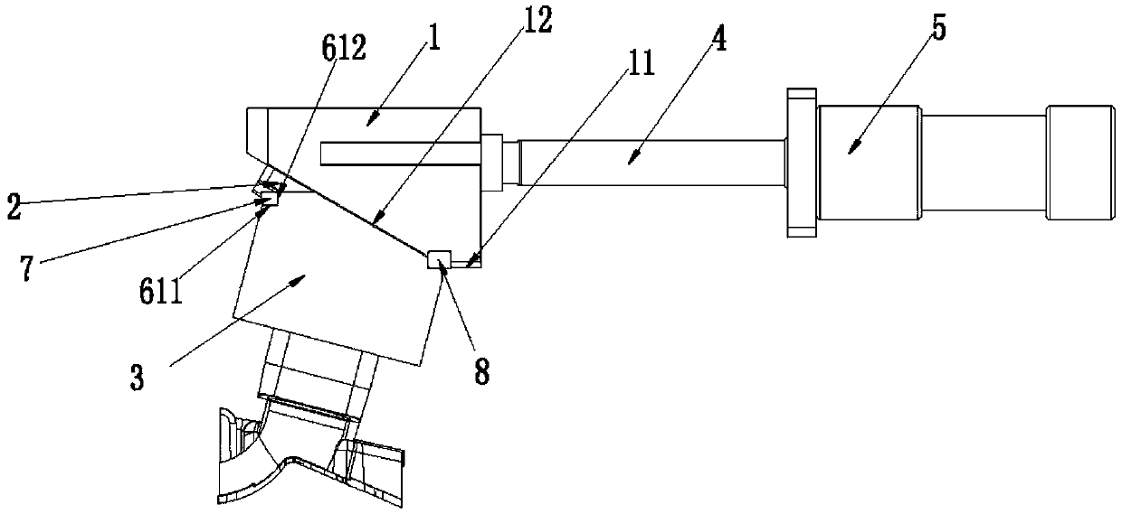
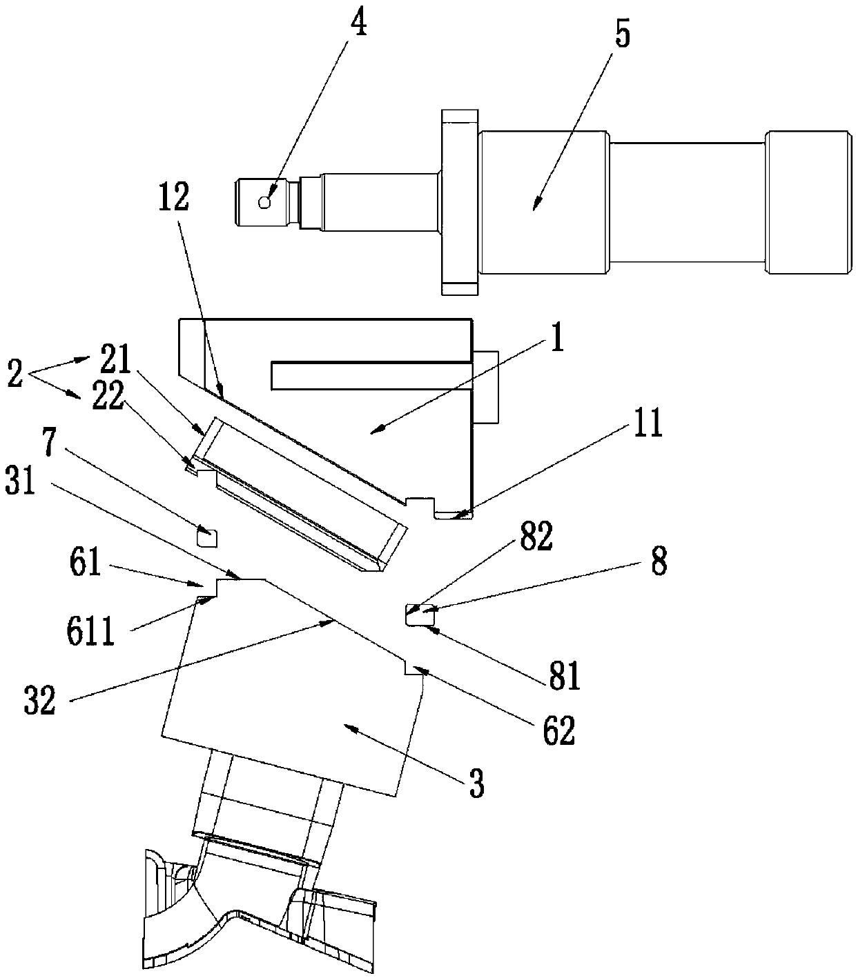
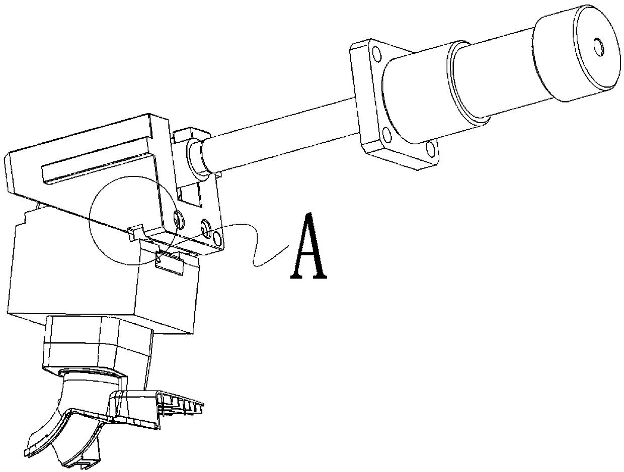
[0021] A specific implementation of the slider anti-retreat structure for an injection mold of the present invention, such as figure 1 and figure 2 As shown, it includes a hydraulic cylinder 5, a linkage seat 1, a slider 3 and a T-shaped block 2. The piston shaft 4 of the hydraulic cylinder 5 is fixedly connected to the linkage seat 1, and the bottom end surface of the linkage seat 1 is formed by a horizontal first plane 11 and an inclined Composed of the first slope 12, the longitudinal section 21 of the T-shaped block 2 is inserted and fixed on the first slope 12 of the linkage seat 1, see Figure 7 , the slider 3 is provided with a T-shaped slot 33. In the assembled state, the transverse section 22 of the T-shaped block 2 is inserted into the T-shaped slot 33 and can slide relative to the T-shaped slot 33. The top surface of the slider 3 is formed by It consists of a second pl...


PUM


Abstract

The invention relates to the technical field of molds, in particular to a sliding block anti-receding structure for an injection mold. The sliding block anti-receding structure for the injection moldcomprises a hydraulic cylinder, a linkage seat, a sliding block and a T-shaped block. A piston shaft of the hydraulic cylinder is fixedly connected with the linkage seat. A longitudinal segment of theT-shaped block is inserted into and fixedly connected to a first bevel of the linkage seat. A T-shaped groove is formed in the sliding block. In a demolding state, a transverse segment of the T-shaped block is inserted into the T-shaped groove and can slide relative to the T-shaped groove. The anti-receding structure further comprises a first locking block and a second locking block which are arranged at the two ends of the linkage seat. In an injection molding state, the sliding block is locked jointly by the first locking block and the second locking block. In the demolding state, the firstlocking block is inserted into the T-shaped groove, and the sliding block slides downwards obliquely along the T-shaped groove. Compared with the prior art, in the injection molding state, the sliding block is propped up jointly by the first locking block and the second locking so that the sliding block is prevented from sliding relative to a sliding seat; and the problem in a previous injectionprocess that the sliding block slides under the action of extrusion force is solved.

Description

technical field [0001] The invention relates to the technical field of moulds, in particular to a slider anti-retreat structure for injection molds. Background technique [0002] The slider is a mold component that can slide perpendicular to the mold opening and closing direction or at a certain angle to the mold opening and closing direction during the mold opening action. When the product structure prevents the mold from being released normally, the slider must be used. In the mold manufacturing process, the design of the core-pulling mechanism of the front mold cylinder is inevitable for many molds. When using this core-pulling mechanism, the clamping force of the injection molding machine is often unable to lock the slider. At this time, the slider is affected. The retreat of the clamping force is the most common failure form of the core-pulling mechanism. The failure of the core-pulling mechanism will lead to the occurrence of defects such as excessive glue, flash, and...

Claims


Application Information

Patent Timeline
IPC IPC(8): B29C45/33
CPCB29C45/33B29C2045/338
Inventor 李政成
Owner 南方佛吉亚汽车部件有限公司
Why Eureka
Try Eureka