Flap arrangement for turbine, turbine, and exhaust gas turbocharger

一种废气涡轮、涡轮机的技术,应用在发动机元件、机器/发动机、升阀等方向,能够解决泄漏、热变形、增加泄漏等问题

Active Publication Date: 2019-04-19
BORGWARNER INC
View PDF7 Cites 1 Cited by
  • Summary
  • Abstract
  • Description
  • Claims
  • Application Information

AI Technical Summary

Problems solved by technology

But since the same temperature does not exist everywhere and the wall thicknesses in the corresponding regions of the turbine casing may differ from each other, the degree of thermal expansion is not the same everywhere
This can cause thermal deformation of the flap seat for the flap assembly in the turbine housing relative to the bore in which the flap assembly is supported
Thermal deformation is problematic as it can cause leaks for such a rigid disc assembly as the rigid disc no longer sits flat on the disc seat
Increased leakage resulting in loss of performance

Method used


Image

  • Flap arrangement for turbine, turbine, and exhaust gas turbocharger
  • Flap arrangement for turbine, turbine, and exhaust gas turbocharger
  • Flap arrangement for turbine, turbine, and exhaust gas turbocharger

Examples


Embodiment Construction

[0022] An exemplary embodiment of a flap arrangement 10 according to the invention as well as a turbomachine with such a flap arrangement 10 and a corresponding exhaust gas turbocharger are described below with the aid of the figures.

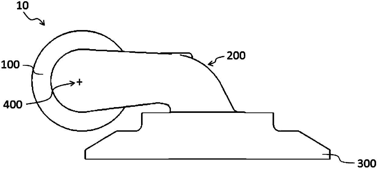
[0023] figure 1 A flap assembly 10 known from the prior art for a turbine of an exhaust gas turbocharger is shown. The flap assembly 10 has a spindle 100 , a lever arm 200 and a flap disc 300 . When used in an exhaust gas turbocharger, the flap assembly 10 is mounted in the turbine housing rotatably about the axis of rotation 400 via the main shaft 100 so that the valve flap assembly 10 can be used to close or release the passage in a targeted manner. Holes, such as through-holes for wastegates.

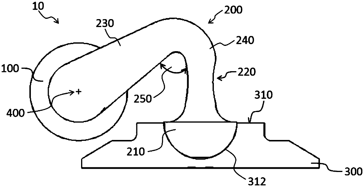
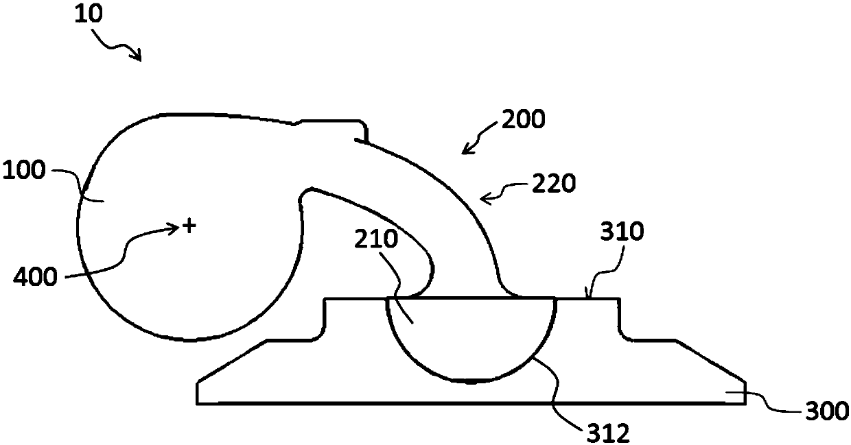
[0024] figure 2 and image 3 An exemplary embodiment according to the invention of a flap assembly 10 for a turbine of an exhaust gas turbocharger, in particular for a wastegate valve of a turbomachine, is shown. The flap assembly according to t...


PUM


Abstract

The invention relates to a flap arrangement for a turbine of a turbocharger, in particular for a wastegate valve of the turbine, having a spindle for mounting the flap arrangement in a rotatable manner in a turbine housing, having a lever arm, wherein the lever arm is coupled to the spindle, and having a flap disk, wherein the flap disk is coupled to the lever arm. At least part of the lever arm is configured elastically such that applying a closing force to the flap arrangement, when the flap disk is in contact with a flap seat in the turbine housing, provides for relative movement of the flap disk in relation to the spindle, in order to compensate for thermal deformation of the turbine housing and / or wear.

Description

technical field [0001] The invention relates to a valve flap assembly for a turbine of an exhaust gas turbocharger and to a turbine and an exhaust gas turbocharger with a corresponding valve flap assembly. Background technique [0002] Known exhaust gas turbochargers have a turbine with a turbine wheel which is driven by the exhaust gas flow of the combustion engine. A compressor wheel arranged on a common shaft with the turbine wheel compresses the fresh air drawn in for the engine, thereby increasing the pressure of the fresh air. This increases the amount of air or oxygen available to the engine for combustion, which in turn leads to an increase in the performance of the combustion engine. Since the turbine wheel is coupled to the compressor wheel, the pressure to be built up always depends on the quantity of exhaust gas delivered. In certain operating states, it is necessary to reduce or adjust the drive energy acting on the compressor. [0003] In particular, wastega...

Claims


Application Information

Patent Timeline
Patent Type & Authority Applications(China)
IPC IPC(8): F01D17/12F02B37/18
CPCF01D17/12F02B37/18F02B37/186F16K1/20Y02T10/12F01D17/145F02B37/183
Inventor J·克瑙夫
Owner BORGWARNER INC
Why Eureka
Try Eureka