Eureka AIR delivers breakthrough ideas for toughest innovation challenges, trusted by R&D personnel around the world.

Magnetic encoder, calibration method and device for magnetic encoder, motor and unmanned aerial vehicle

A technology of magnetic encoder and calibration method, which is applied in the direction of transmitting sensing components, measuring devices, instruments, etc. by using electric/magnetic devices, and can solve problems such as unfavorable miniaturization of the pan/tilt design

Active Publication Date: 2019-04-19
GUANGZHOU XAIRCRAFT TECH CO LTD
View PDF6 Cites 14 Cited by
  • Summary
  • Abstract
  • Description
  • Claims
  • Application Information

AI Technical Summary

Problems solved by technology

[0003] However, when the magnetic encoder is used in scenarios such as the gimbal of an unmanned aerial vehicle, a miniaturized design is often required
The existing installation method of the magnetic sensor and the magnet facing each other usually requires a space of about 1.5-3mm for installation, which is not conducive to the miniaturization design of the gimbal

Method used


Image

  • Magnetic encoder, calibration method and device for magnetic encoder, motor and unmanned aerial vehicle
  • Magnetic encoder, calibration method and device for magnetic encoder, motor and unmanned aerial vehicle
  • Magnetic encoder, calibration method and device for magnetic encoder, motor and unmanned aerial vehicle

Examples


Embodiment Construction

[0039] Specific embodiments of the present invention will be described in detail below in conjunction with the accompanying drawings. It should be understood that the specific embodiments described here are only used to illustrate and explain the present invention, and are not intended to limit the present invention.

[0040] It should be noted that if there is a directional indication (such as up, down, left, right, front, back...) in the embodiment of the present invention, the directional indication is only used to explain the position in a certain posture (as shown in the accompanying drawing). If the specific posture changes, the directional indication will also change accordingly.

[0041] In addition, if there are descriptions involving "first", "second" and so on in the embodiments of the present invention, the descriptions of "first", "second" and so on are only for descriptive purposes, and should not be understood as indicating or implying Its relative importance or ...


PUM


Abstract

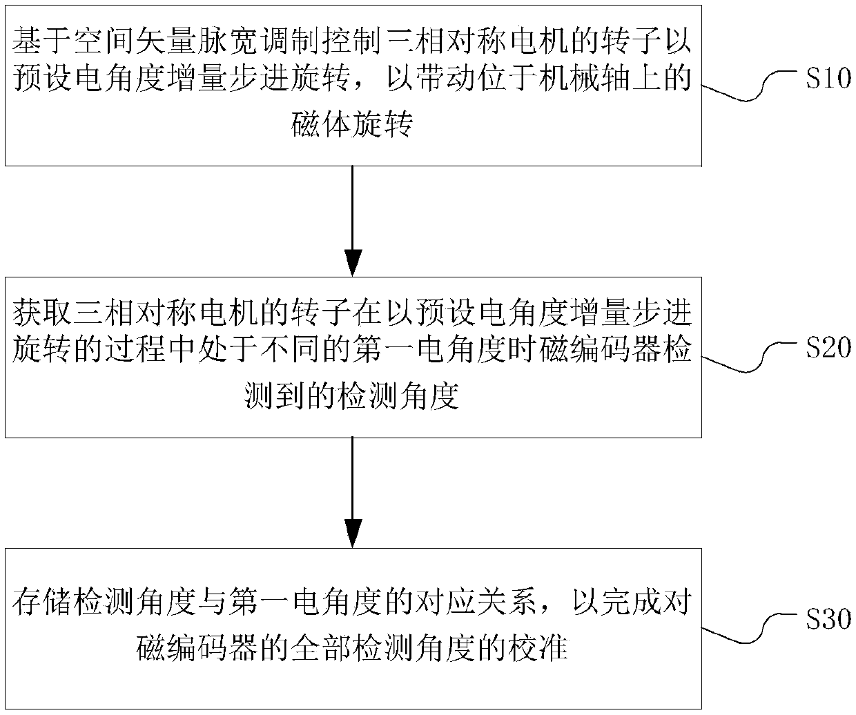
An embodiment of the invention provides a magnetic encoder, a calibration method and device for the magnetic encoder, a motor and an unmanned aerial vehicle, and belongs to the field of electronic control. The calibration method herein comprises: controlling a rotor of a three-phase symmetric motor to rotate stepwise under a preset electrical angle increment on the basis of space vector pulse width modulation, so that a magnet on a mechanical shaft is driven to rotate; acquiring detection angles detected by the magnetic encoder when the rotor is at different first electrical angles when rotating stepwise under the preset electrical angle increment; storing a correspondence between the detection angles and the first electrical angles so as to calibrate the magnetic encoder. Therefore, by making use of the characteristic that the electrical angle of the three-phase symmetric motor can be accurately controlled through space vector pulse width modulation, calibration between the detectionangle of a lateral magnetic encoder and the electrical angle of the three-phase symmetric motor can be completed; the lateral magnetic encoder is applicable to the detection of the angle of the three-phase symmetric motor; therefore, miniature design of the devices, such as a head, is achieved.

Description

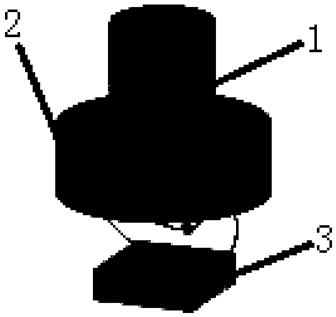
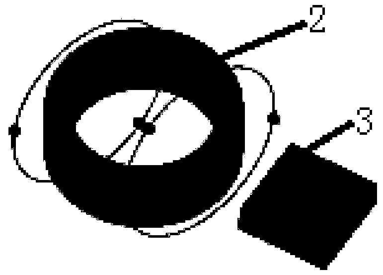
technical field [0001] The invention relates to the field of electronic control, in particular to a magnetic encoder, its calibration method and calibration device, a motor and an unmanned aerial vehicle. Background technique [0002] Magnetic encoders are widely used as sensors in angle and position detection due to their non-contact, small size, low cost, simple structure and high reliability. In applications involving motor positioning, such as gimbals, magnetic encoding schemes are usually used to detect the angle and position of the motor. Such as figure 1 As shown, in the current magnetic encoder, the magnetic sensor is usually used facing the magnet. The advantage of this is that the magnetic field generated by the magnet is evenly distributed at the magnetic sensor, and the angular output of the magnetic sensor is linear to the actual mechanical angle of the motor. In this way, the magnetic encoder can basically not be calibrated, or it can be calibrated by connect...

Claims


Application Information

Patent Timeline
IPC IPC(8): G01D5/244G01D18/00
CPCG01D5/24423G01D18/00
Inventor 于江涛
Owner GUANGZHOU XAIRCRAFT TECH CO LTD
Why Eureka
Eureka Blog
Learn More