
Running belt driving mechanism of treadmill

A driving mechanism and treadmill technology, applied in the field of treadmills, can solve problems such as limited space occupied by accessories, increased production and transportation costs, and reduced service life of treadmills, so as to save space, increase maintenance costs, and reduce production and repairs cost effect

Pending Publication Date: 2019-04-23
泊康科技股份有限公司
View PDF0 Cites 2 Cited by
  • Summary
  • Abstract
  • Description
  • Claims
  • Application Information

AI Technical Summary

Problems solved by technology

[0002] At present, most treadmills on the market use a motor installed at the front end of the treadmill, and the motor rotates through the belt to drive the roller to rotate. Because the installation of the motor occupies a large amount of space at the front end of the treadmill, the space occupied by other accessories is limited, and the front protective cover is enlarged. Production and Increased shipping costs
At the same time, the belt is an elastic body, which is elastically deformed by tension during the transmission process. The elastic deformation of the belt will cause the sliding between the belt and the pulley, resulting in speed loss, reducing the transmission efficiency of the motor, and increasing the wear of the belt. Later maintenance Increased costs and reduced treadmill lifespan

Method used


Image

  • Running belt driving mechanism of treadmill
  • Running belt driving mechanism of treadmill
  • Running belt driving mechanism of treadmill

Examples


Embodiment Construction

[0023] The present invention will be described in further detail below in conjunction with the examples.

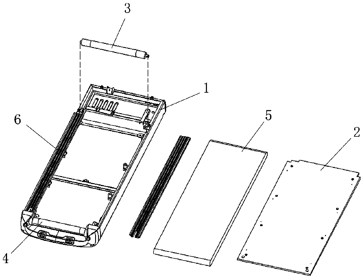
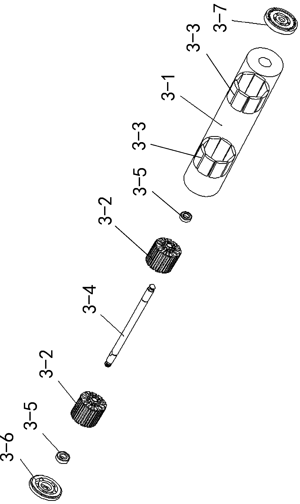
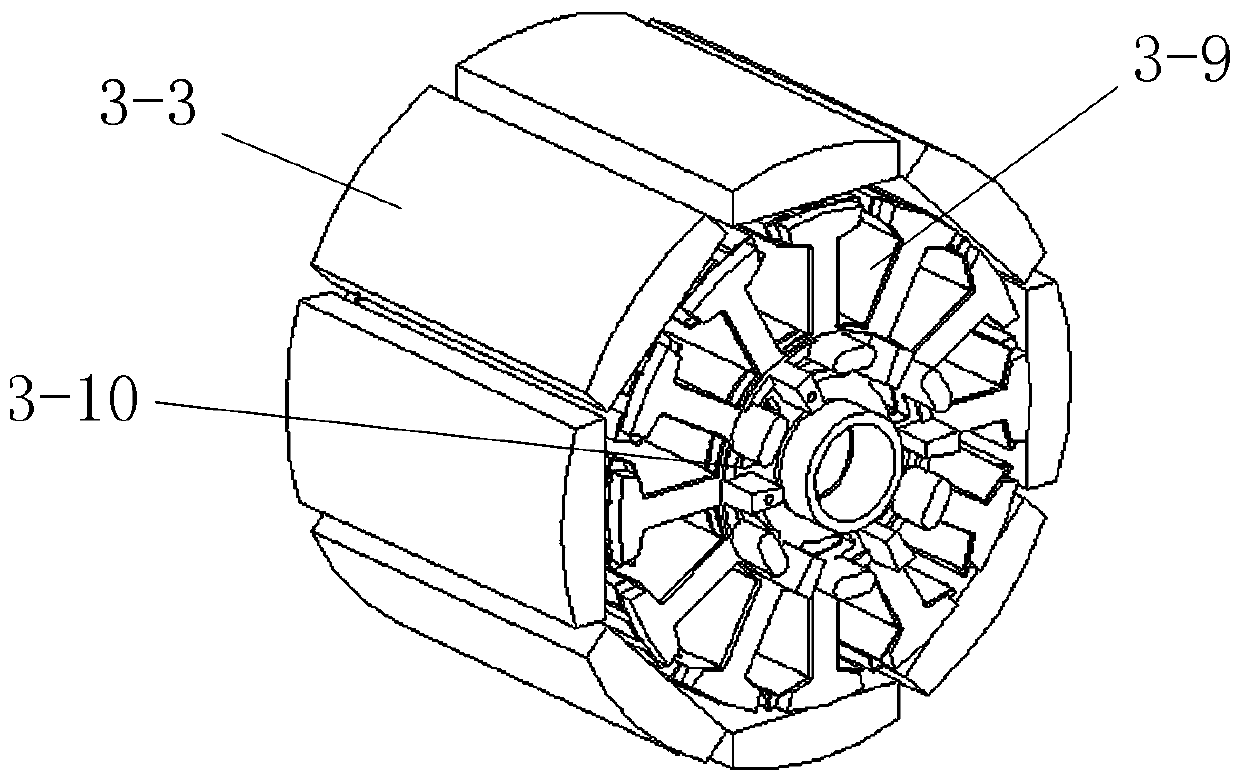
[0024] Such as Figure 1 to Figure 4 As shown, a running belt driving mechanism of a treadmill includes a bottom frame 1, a running board 2, a driving roller 3, a driven roller 4, and an endless running belt 5. The running board 2 is fixed on the bottom frame 1, and the driving roller 3 and the driven roller 4 are respectively installed on the bottom frame 1 on the front and rear sides of the running board 2. There are side bars 6 on both sides of the bottom frame 1. The endless running belt 5 is sleeved on the driving roller 3 and the driven roller 4. 2 is located in the endless running belt 5. The driving drum 3 includes a cylinder 3-1, and an outer rotor brushless motor is arranged in the cylinder 3-1. The outer rotor brushless motor includes a stator coil 3-2 and a rotor The magnet piece 3-3 and the motor shaft 3-4, the stator coil 3-2 is installed on the motor shaft 3-...


PUM


Abstract

The invention discloses a running belt driving mechanism of a treadmill. The mechanism includes chassis, a running board, a driving roller, a driven roller and an annular running belt. The running board is fixed on the chassis, and the driving roller and the driven roller are installed on the chassis installed on the front and rear sides of the running board, the two sides of each chassis are provided with edge strips, the annular running belt sleeves the driving roller and the driven roller, the running board is located in the annular running belt, the driving roller includes a roller body, the roller body is internally provided with an outer rotor brushless motor, the outer rotor brushless motor includes a stator coil, a rotor magnet sheet and a motor shaft, the stator coil is installedon the motor shaft, the rotor magnet sheet is fixed on the inner wall of the roller body, bearings are installed at the two ends of the motor shaft, and the two ends of the roller body are provided with a front end cover and a rear end cover provided with fan blade type ventilation holes. The cost is reduced, the production and maintenance cost is reduced, the transmission efficiency of the motoris improved, and the service life of the treadmill is prolonged.

Description

Technical field [0001] The invention relates to a treadmill, in particular to a running belt driving mechanism of the treadmill. Background technique [0002] At present, most treadmills on the market use motors installed at the front end of the treadmill, and the rotation of the motor drives the drum to rotate through a belt. Because the installation of the motor takes up a lot of space at the front end of the treadmill, the space occupied by other accessories is limited, and the front end protection cover is enlarged. Increase in transportation costs. At the same time, the belt is an elastic body, which is elastically deformed by pulling force during the transmission process. The elastic deformation of the belt will cause the sliding between the belt and the pulley, which will cause speed loss, reduce the transmission efficiency of the motor, increase the wear of the belt, and later maintain The cost increases and the service life of the treadmill is reduced. Therefore, the d...

Claims


Application Information

Patent Timeline
Patent Type & Authority Applications(China)
IPC IPC(8): A63B22/02H02K7/14H02K29/14
CPCA63B22/0235H02K7/14H02K29/14
Inventor 潘岩君朱晓明汪安生
Owner 泊康科技股份有限公司
Learn More