
Upper sawing panel saw device

A panel saw and up-saw technology, which is applied to the field of up-saw panel saw devices, can solve the problems that the sawing speed is difficult to increase, affect product quality, cannot be used, etc., so as to reduce the requirements of saw blades and increase the output of saw blades. , The effect of prolonging the sharpening cycle

Pending Publication Date: 2019-04-23
上海华鄂工程技术有限公司
View PDF7 Cites 0 Cited by
  • Summary
  • Abstract
  • Description
  • Claims
  • Application Information

AI Technical Summary

Problems solved by technology

[0007] 3. When multiple sawing materials are sawed and processed, the surface decoration material on the lower sawed edge of the upper layer material bursts, that is, the sawed edge has different degrees of cracks on the lower surface, which seriously affects the product quality and even cannot be used;
[0008] 4. It is difficult to increase the sawing speed

Method used


Image

  • Upper sawing panel saw device
  • Upper sawing panel saw device

Examples


Embodiment 1

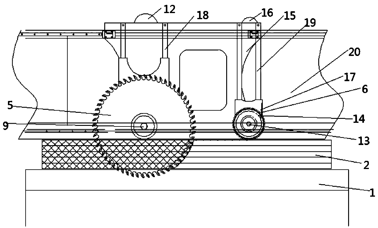
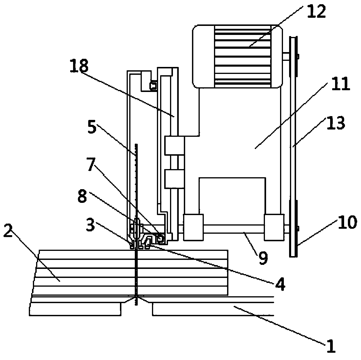
[0020] Such as figure 1 and figure 2 The upper-saw panel saw device shown includes: a table top 1, a sawing workpiece 2 is placed on the upper part of the table 1 (stacked in multiple layers), and the upper surface of the sawing workpiece 2 is pressed by the main pressure beam 3, The rear side of the main pressure beam 3 is provided with an auxiliary pressure beam 4, a main saw blade 5 and a groove saw blade 6 are arranged between the main pressure beam 3, and a linear guide rail 7 in the sawing direction is installed on the rear side, and the straight line The inside of the guide rail 7 is equipped with a slider 8 that moves along the linear guide rail. The main saw blade 5 is connected to the main saw shaft 9 through flange compression, and the main saw shaft 9 is fixed on the main saw mechanism 11. The motor 12 is fixed on the upper part of the mechanism 11, the motor 12 is driven by a belt with the main saw shaft 9, the motor 12 is connected with the main saw wheel 10 th...

Embodiment 2

[0022] Such as figure 1 and figure 2 The upper-saw panel saw device shown includes: a table top 1, a sawing workpiece 2 is placed on the upper part of the table top 1, and the upper surface of the sawing workpiece 2 is pressed by a main pressure beam 3, and the main pressure beam 3 The rear side is provided with an auxiliary pressure beam 4, the main saw blade 5 and the groove saw blade 6 are arranged between the main pressure beams 3, and the linear guide rail 7 in the sawing direction is installed on the rear side, and the linear guide rail 7 is equipped with The slider 8 moving along the linear guide rail, the main saw blade 5 is connected with the main saw wheel 10 through the main saw shaft 9, the main saw shaft 9 is fixed on the main saw mechanism 11, and the upper part of the main saw mechanism 11 is fixed Motor 12, the motor 12 is driven by a belt with the main saw shaft 9, the motor 12 is connected with the main saw runner 10 through a belt 13, and the slot saw blad...


PUM


Abstract

The invention discloses an upper sawing panel saw device. The device comprises a table-board, wherein a saw cutting workpiece is placed on the table-board; the upper surface of the saw-cutting workpiece is pressed by main pressure beams; an auxiliary pressure beam is arranged at the rear side of each main pressure beam; a main saw web and a slot saw web are arranged between the main pressure beams; linear guide rails are arranged at the rear side in the sawing and cutting direction; a sliding block moving along the linear guide rails is arranged in each linear guide rail; the main saw web is connected to a main saw shaft by flange pressing; the main saw shaft is fixed on a main saw mechanism; a motor is fixed on the upper portion of the main saw mechanism; the motor and a main saw rotatingwheel are connected through a belt; the slot saw web is connected with a slot saw rotating wheel through a rotating shaft I and fixed on a slot saw mechanism; a motor I is fixed on the upper portionof the slot saw mechanism and the motor I is connected with the slot saw rotating wheel through a belt I; the main saw mechanism is connected with main saw web lifting guide rails and the slot saw mechanism is connected with slot saw web lifting guide rails; and the main saw web lifting guide rails and the slot saw web lifting guide rails are fixed on a support of the panel saw.

Description

technical field [0001] The invention relates to the field of panel saws, in particular to an upper saw type panel saw device. Background technique [0002] Because the boards used for furniture or props require special performance or surface effects, many of them are pasted with fireproof boards or melamine-impregnated papers. In order to improve sawing efficiency and sawing quality, cutting equipment has many requirements. In order to improve efficiency, when the machine is cutting, generally multiple plates are stacked and sawed at the same time to improve efficiency; however, this increases the difficulty of sawing quality. Due to the material During the compounding process, there are large differences between the surface layer and the core layer, the middle and the surrounding of the board, resulting in inconsistencies in the thickness and processing performance of the same batch of processed materials during storage and processing. When multiple boards are stacked and s...

Claims


Application Information

Patent Timeline
Patent Type & Authority Applications(China)
IPC IPC(8): B27B5/06B27B5/29B27G19/02
CPCB27B5/06B27B5/29B27G19/02
Inventor 喻诗浩余炳华刘剑朱治平朱学文郝云聪
Owner 上海华鄂工程技术有限公司
Features
  • Generate Ideas
  • Intellectual Property
  • Life Sciences
  • Materials
  • Tech Scout
  • Unparalleled Data Quality
  • Higher Quality Content
  • 60% Fewer Hallucinations
Learn More