
A plastic granulator discharge equipment with an anti-clogging structure

A granulator, anti-clogging technology, used in packaging, loading/unloading, large containers, etc., can solve the problems of blockage of the discharge port, troublesome cleaning, extrusion and accumulation of plastic particles, etc., to achieve up and down reciprocating movement, structural setting Reasonable and avoid offset effect

Active Publication Date: 2020-11-24
安徽木尔萨塑业科技有限公司
View PDF13 Cites 0 Cited by
  • Summary
  • Abstract
  • Description
  • Claims
  • Application Information

AI Technical Summary

Problems solved by technology

[0003] 1. After the traditional plastic granulator completes the processing of plastic particles, it needs to be discharged outward. A large number of plastic particles gather at the discharge port, which is easy to cause plastic particles to squeeze and accumulate, resulting in blockage of the discharge port. , at this time, workers are required to dredge, and the dredging process directly affects the overall production efficiency of the plastic granulator;
[0004] 2. The discharge port of the traditional plastic particle granulator is fixedly installed, and a large amount of powder or dust sticks to the surface of the produced plastic particles, which is easy to adhere to the inner wall of the discharge device during the discharge process, and it is troublesome to clean;

Method used


Image

  • A plastic granulator discharge equipment with an anti-clogging structure
  • A plastic granulator discharge equipment with an anti-clogging structure
  • A plastic granulator discharge equipment with an anti-clogging structure

Examples


Embodiment Construction

[0021] The following will clearly and completely describe the technical solutions in the embodiments of the present invention with reference to the accompanying drawings in the embodiments of the present invention. Obviously, the described embodiments are only some of the embodiments of the present invention, not all of them. Based on the embodiments of the present invention, all other embodiments obtained by persons of ordinary skill in the art without making creative efforts belong to the protection scope of the present invention.

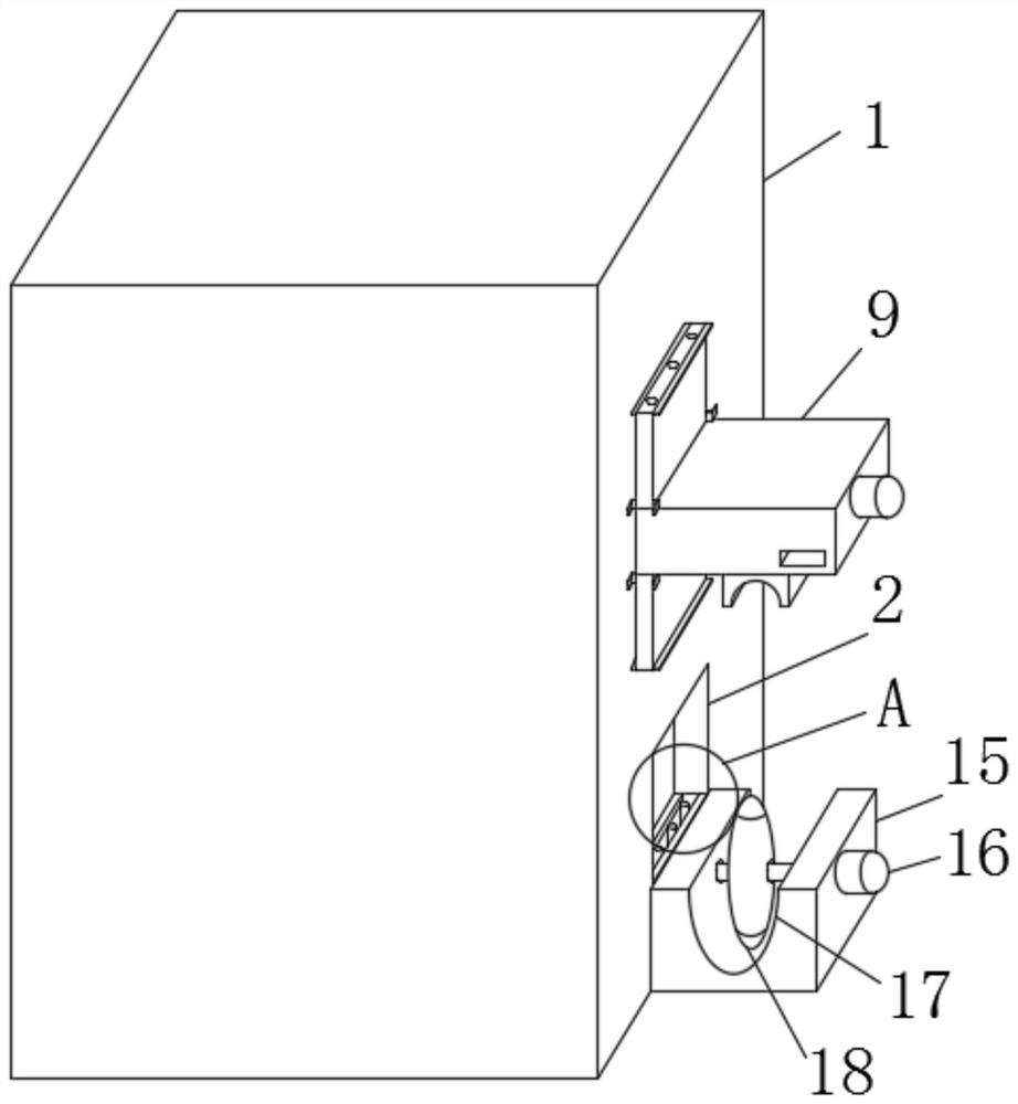
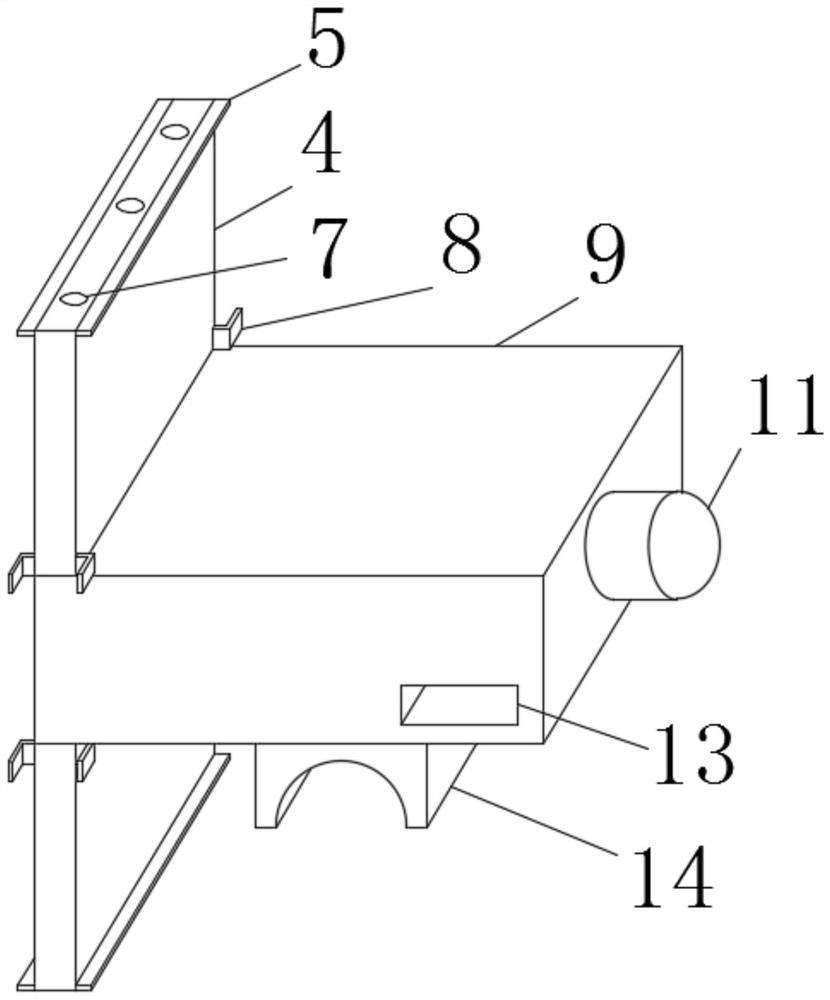
[0022] see Figure 1 to Figure 5 , the present invention provides a technical solution: a plastic granulator discharge device with an anti-clogging structure, comprising a plastic granulator 1 and a discharge device body 9, the side wall of the plastic granulator 1 is provided with a discharge The upper and lower inner walls of the feed port 2 and the discharge port 2 are provided with vertical chutes 3, and the interior of the two vertical chute...


PUM


Abstract

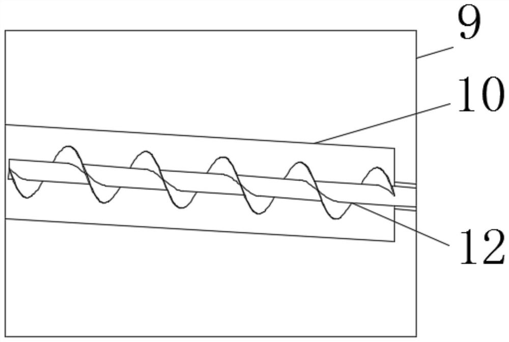
The invention discloses a plastic granulator discharging facility with an anti-blocking structure. The plastic granulator discharging facility with the anti-blocking structure comprises a plastic granulator and a discharging facility body. A discharging outlet is formed in the side wall of the plastic granulator. Perpendicular sliding grooves are formed in the upper inner wall and the lower innerwall of the discharging outlet, and limiting sliding plates are connected with the interiors of the two perpendicular sliding grooves in a sliding mode. The end faces of the limiting sliding plates are located on the end faces of the interiors of the perpendicular sliding grooves, and baffles are fixedly connected with the end faces of the limiting sliding plates. Locating columns are fixedly connected with the interiors of the perpendicular sliding grooves and inserted into butt joint insertion holes in a connection mode, and the butt joint insertion holes are formed in the surfaces of the limiting sliding plates. Enclosure clamping plates are fixedly connected with the plate surfaces of the limiting sliding plates, and the discharging facility body is fixedly connected between the two limiting sliding plates. According to the plastic granulator discharging facility with the anti-blocking structure, the discharging facility is arranged in the discharging outlet, a spiral blade material guide pipe is additionally arranged inside the discharging facility and continuously guides plastic particles, and the plastic particles are prevented from blocking the facility in the discharging process.

Description

technical field [0001] The invention relates to the technical field of granulators, in particular to a plastic granulator discharge device with an anti-clogging structure. Background technique [0002] A plastic granulator is a molding machine that can manufacture materials into specific shapes. The plastic granulators currently in use on the market mainly include a drive device, a feeding mechanism, a plastic entraining device, a primary crushing device, a conveying device, Secondary crushing equipment and finished product collection device, the driving device is connected with the feeding mechanism, the plastic rolling device is set at the bottom of the feeding mechanism, and the plastic rolling device is connected with the rotating shaft of the driving device, and the feeding mechanism is also connected with the primary crushing equipment , the primary crushing equipment is connected with the secondary crushing equipment through the transmission device, the secondary crus...

Claims


Application Information

Patent Timeline
Patent Type & Authority Patents(China)
IPC IPC(8): B29B9/06B65D88/68B65G69/08
CPCB29B9/06B65D88/68B65G69/08
Inventor 刘冀周
Owner 安徽木尔萨塑业科技有限公司
Learn More