Intelligent door lock mechanical and electrical separation device

An electromechanical separation, intelligent door lock technology, applied in the direction of building locks, non-mechanical transmission-operated locks, buildings, etc., can solve the problems of occupying the lock body, excessive position space, and complex internal structure of the fully automatic lock body. And the effect of simple processing and reasonable setting

Pending Publication Date: 2019-04-23
深圳市优点科技有限公司
View PDF0 Cites 4 Cited by
  • Summary
  • Abstract
  • Description
  • Claims
  • Application Information

AI Technical Summary

Problems solved by technology

[0004] Aiming at the deficiencies in the prior art, the present invention provides an electromechanical separation device for intelligent door locks, which solves the problem that some automatic lock bodies do not have manual mechanical unlocking function, or the internal structure of automatic lock bodies with manual mechanical unlocking function is very abnormal. Complicated, the problem of occupying too much space in the lock body

Method used


Image

  • Intelligent door lock mechanical and electrical separation device
  • Intelligent door lock mechanical and electrical separation device
  • Intelligent door lock mechanical and electrical separation device

Examples


Embodiment 1

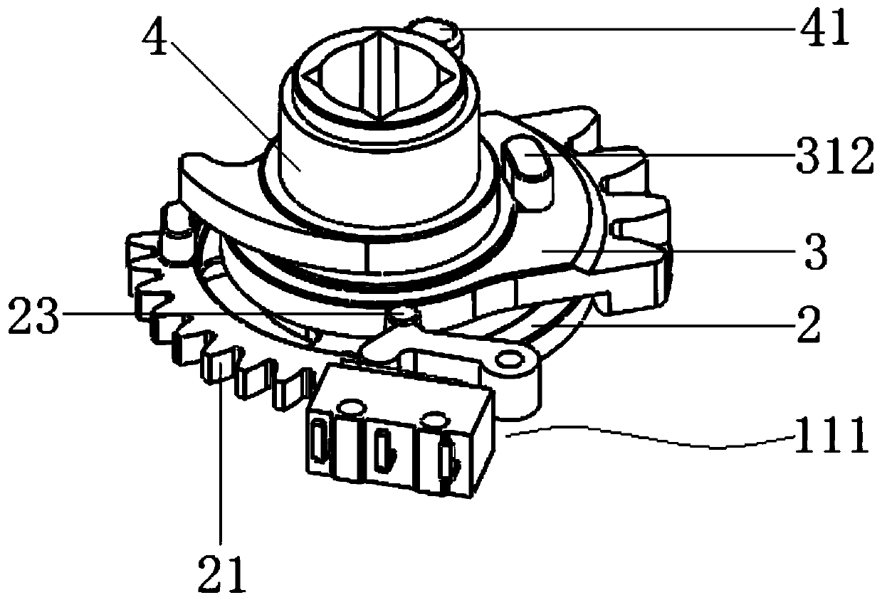
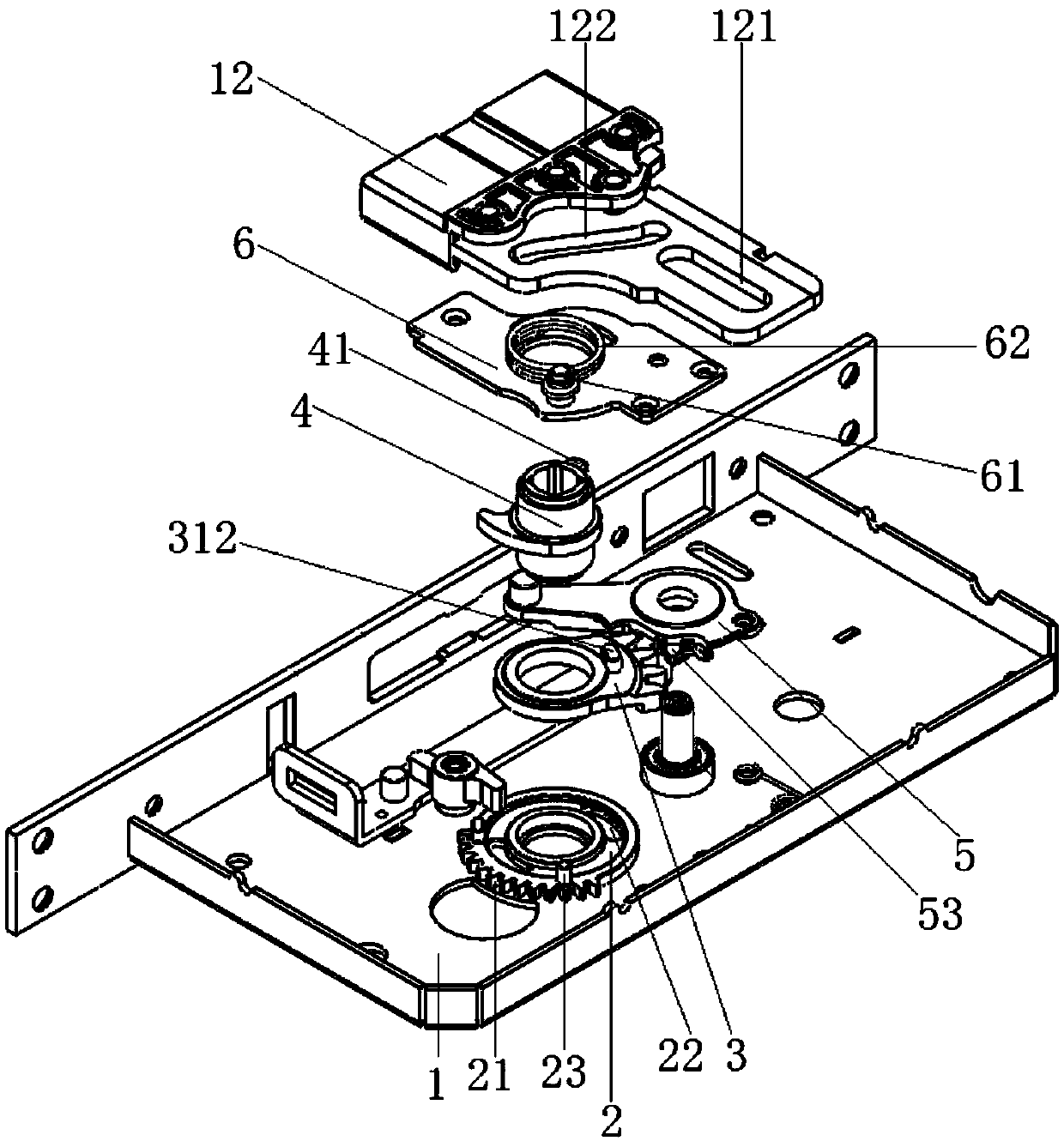
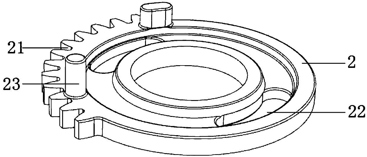
[0037] Embodiment 1 is to use the motor module 11 to electrically unlock the lock. The process is: the motor of the motor module 11 is started, and the output gear of the motor module 11 meshes with the first tooth portion 21 of the first driving part 2, and then drives the first driving part 2 to rotate. , because the first boss 311 snaps into the transmission groove 22 of the first driving member 2, so the first driving member 2 further drives the first transmission member 3 to rotate, and the first transmission member 3 finally drives the second transmission member 5 to rotate, and the second transmission member 5 rotates. The second transmission part 5 then controls the contraction of the main lock tongue 12. When the main lock tongue 12 is retracted in place, the motor of the motor module 11 reverses, and then drives the first boss 311 of the first transmission part 3 to be in the transmission groove of the first drive part 2. 22 at the middle position.

Embodiment 2

[0038] Embodiment 2 is manual mechanical unlocking, and its process is: the second driving part 4 is connected with the conventional lock cylinder, when the lock core drives the second driving part 4 to rotate, the stopper 41 on the outer edge of the second driving part 4 pushes the first transmission The second boss 312 on the top of the part 3 further makes the first transmission part 3 rotate, finally drives the second transmission part 5 to rotate, and then controls the main lock tongue 12 to shrink.


PUM


Abstract

The invention relates to the technical field of lock bodies and discloses an intelligent door lock mechanical and electrical separation device. The intelligent door lock mechanical and electrical separation device comprises a first driving part, a first transmission part, a second driving part, a second transmission part and a motor module, by means of the design of a mechanical and electrical separation design, automatic unlocking can be performed and manual mechanical unlocking can also be performed, when electric unlocking is performed, the first driving part is firstly driven to rotate through the motor module, the first transmission part is sequentially driven to rotate by the first driving part and drives the second transmission part to rotate, and then stretching and contracting ofa main lock tongue are controlled; when the manual mechanical unlocking is performed, a lock cylinder drives the second driving part to rotate, the second driving part sequentially drives the second transmission part to rotate, the contracting of the main lock tongue is controlled, therefore, the intelligent door lock mechanical and electrical separation device has the functions of the manual mechanical unlocking and the motor automatic unlocking, and the functions of the manual mechanical unlocking and the motor automatic unlocking do not affect each other at the same time; and the intelligent door lock mechanical and electrical separation device is simple in structure and easy to machine, too much position space inside the lock body is not occupied, and the intelligent door lock mechanical and electrical separation device can be reasonably arranged with other components.

Description

technical field [0001] The invention relates to the field of lock body technology, in particular to an electromechanical separation device for an intelligent door lock. Background technique [0002] There are two types of fully automatic lock bodies on the market, with manual unlocking and without manual unlocking. The fully automatic lock body without manual unlocking cannot realize manual and quick unlocking inside the door in an emergency, and there are potential safety hazards; while the existing ones with manual unlocking The unlocked fully automatic lock body is very complex in structure, that is, the motor automatic unlocking device and the manual mechanical unlocking structure are set separately, not only the structure is complex, but also occupies too much space in the lock body, resulting in the compact arrangement of other components and difficult processing and high cost. Contents of the invention [0003] (1) Solved technical problems [0004] Aiming at the ...

Claims


Application Information

Patent Timeline
Patent Type & Authority Applications(China)
IPC IPC(8): E05B47/00E05B63/00
CPCE05B47/0012E05B47/026E05B63/0065E05B2047/0021E05B2047/0072
Inventor 张宏练傅永
Owner 深圳市优点科技有限公司
Why Eureka
Try Eureka