
Microwave darkroom with microwave absorbing ridges

A technology of microwave anechoic chamber and ridge, which is applied in the field of microwave anechoic chamber and can solve the problems of difficult realization of absorbing materials and long wavelength of electromagnetic waves.

Inactive Publication Date: 2019-04-23
THE RES INST FOR SPECIAL STRUCTURES OF AERONAUTICAL COMPOSITE AVIC
View PDF5 Cites 0 Cited by
  • Summary
  • Abstract
  • Description
  • Claims
  • Application Information

AI Technical Summary

Problems solved by technology

[0003] At present, microwave anechoic chambers are mostly rectangular anechoic chambers. The performance advantages of rectangular microwave anechoic chambers and their geometry, size, quiet zone requirements, and microwave-absorbing materials are comprehensively designed in order to expect their microwave performance indicators. For low-frequency bands, due to the long wavelength of electromagnetic waves, It is difficult to realize 3λ absorbing materials for engineering applications

Method used


Image

  • Microwave darkroom with microwave absorbing ridges
  • Microwave darkroom with microwave absorbing ridges

Examples


Embodiment Construction

[0010] Below in conjunction with accompanying drawing and embodiment the present invention will be further described:

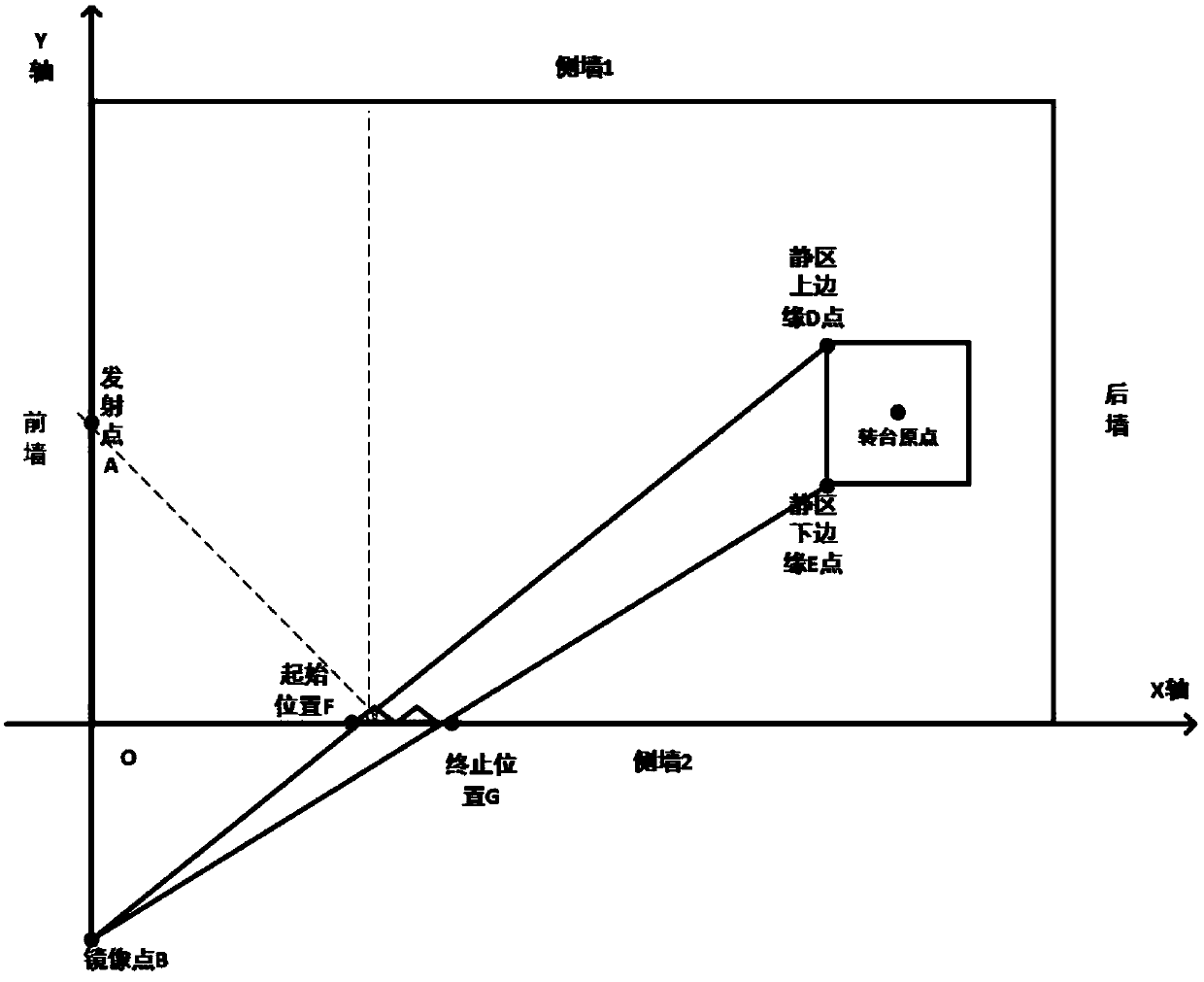
[0011] 1) Assuming that the current size of the microwave anechoic chamber is 35m×18m×18m, then establish a rectangular coordinate system based on the size of the microwave anechoic chamber as shown in the attached figure.

[0012] 2) Take the location of the launch point as the front wall, take the position opposite the launch point, that is, the quiet zone, as the rear wall, take the left-hand position of the launch point along the course as side wall 1, and the right-hand position as side wall 2.

[0013] 3) Set the intersection point of the side wall 2 and the front wall of the microwave anechoic chamber as the coordinate origin point O, the side wall 2 as the surface to be laid with the absorbing long foundation as the X-axis, the wall where the transmitting antenna is located as the Y-axis, and the Z-axis as the height Direction, this calculation proces...


PUM


Abstract

The invention belongs to the technical field of microwave radio frequency and test measurement, and relates to a microwave darkroom with microwave absorbing ridges. With the direction facing a launching point as the reference, the ridges are laid on the ground, the top and / or the side wall of the microwave darkroom, and the laying position of the ridges is determined according to the following method, firstly, the position of a dead zone is determined, and a microwave absorbing ridge laying plane is used as a symmetry plane, a mirror point of the launching point is determined, the mirror pointof the launching point is connected with the two edges of the dead zone, the two connection lines form intersections with the microwave absorbing ridge laying plane, and a connection line of the twointersections is the microwave absorbing ridge laying plane. A new structural design which improves the electromagnetic environment of the microwave darkroom is provided.

Description

technical field [0001] The invention belongs to the technical field of microwave radio frequency and test measurement, and relates to a microwave anechoic chamber with wave-absorbing ridges. Background technique [0002] The two basic functions of the microwave anechoic chamber are to form a non-reflection area indoors and to isolate the interference of external electromagnetic waves. It is an open space environment for simulating the propagation of electromagnetic waves. The test system provides an excellent test environment, and has been paid more and more attention by the scientific community. [0003] At present, microwave anechoic chambers are mostly rectangular anechoic chambers. The performance advantages of rectangular microwave anechoic chambers and their geometry, size, quiet zone requirements, and microwave-absorbing materials are comprehensively designed in order to expect their microwave performance indicators. For low-frequency bands, due to the long wavelength...

Claims


Application Information

Patent Timeline
IPC IPC(8): G01R29/10
CPCG01R29/105
Inventor 赵代岳许群
Owner THE RES INST FOR SPECIAL STRUCTURES OF AERONAUTICAL COMPOSITE AVIC
Learn More