Parachute type seismograph and seismic array layout method

A seismograph and drop-type technology, which is applied in the field of seismic detection devices, parachute-type seismographs, and seismic array layout, can solve the problems of endangering the life, health and safety of relevant personnel, and the difficulty of seismic array layout, so as to reduce the construction cost. Risk, high work efficiency, effect of improving accuracy

Inactive Publication Date: 2019-04-23
CHINA UNIV OF GEOSCIENCES (BEIJING)
View PDF10 Cites 4 Cited by
  • Summary
  • Abstract
  • Description
  • Claims
  • Application Information

AI Technical Summary

Problems solved by technology

The traditional way of deploying seismic arrays is usually to manually deploy seismometers one by one in the area to be detected. However, in areas with complex and harsh environments such as desert Go...

Method used


Image

  • Parachute type seismograph and seismic array layout method
  • Parachute type seismograph and seismic array layout method
  • Parachute type seismograph and seismic array layout method

Examples


Embodiment 1

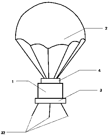
[0028] This embodiment provides a specific structure of a parachute seismograph, such as figure 1 As shown, it includes a body 1 with a cylindrical shape as a whole. The body 1 is provided with core components for seismic measurement, including seismic data measurement and recording devices, communication devices and power supply devices (preferably a combined power supply device of solar cells and lithium batteries), These devices all use mature technology in the field of seismic surveying. Preferably, the main body 1 adopts a metal or plastic shell structure with a waterproof and wind-proof function to protect the internal equipment to meet the requirements of use in the wild natural environment. In order to meet the needs of parachuting by airdrop, a parachute 2 is provided on the top of the seismograph body 1 and a position adjustment device 3 is provided on the bottom. The purpose of using the parachute 2 is to ensure that the seismograph landed on the ground smoothly and ...

Embodiment 2

[0033] This embodiment provides a method for setting up a seismic array using the parachute seismograph described in embodiment 1, such as Figure 7 to Figure 8 As shown, including the following steps:

[0034] (1) Pre-set the exploration area according to the exploration target; carry the parachute seismograph 7 through the flight platform 6 and fly to the sky above the exploration area 5;

[0035] (2) Put the parachute seismograph 7 in accordance with the requirements of the layout of the seismic array; by parachuting, the resistance of the parachute can be fully utilized to ensure the landing direction of the seismic array, thereby reducing the speed of the seismic array when it is falling , To reduce the impact force when the seismic array touches the ground;

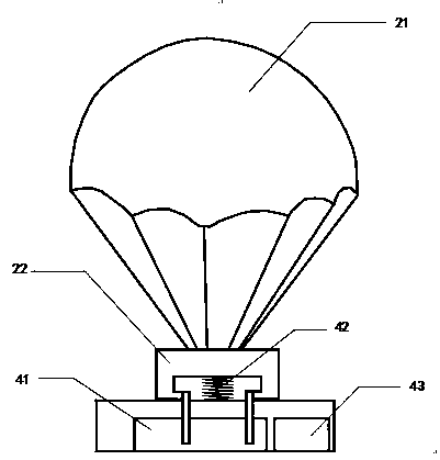
[0036] (3) After the parachute seismograph 7 has landed, the parachute 2 of the parachute seismograph is separated from the main body 1 under the action of the detachment mechanism 4; preventing the parachute from coverin...


PUM


Abstract

A parachute type seismograph comprises a body which is internally provided with a seismic data measuring and recording device, a communication device and a power supply device, wherein a parachute isarranged at the top of the body; and a position adjusting device is arranged at the bottom of the body. According to the parachute type seismograph and a seismic array layout method involved in the invention, a traditional artificial ground layout is replaced by an aerial throwing layout, so that the limitation of road traffic and construction environment is broken through; and seismic array layout work can be carried out in depopulated zones such as gobi desert and alpine snowfield, so that field construction risk is reduced and the working efficiency is high. The adopted parachute type seismograph has the functions of parachute landing and automatic parachute separation, and can prevent unstable posture of the seismograph due to coverage of the seismograph body by the parachute or the action of wind force while providing the buffering and landing functions for the seismograph; and the parachute type seismograph has a heeling condition and an azimuth automatic adjusting function, thereby improving the accuracy of seismic surveys.

Description

Technical field [0001] The invention belongs to the technical field of seismic detection, and relates to a seismic detection device, in particular to a parachute seismograph, and a seismic array layout method using the parachute seismograph. Background technique [0002] In recent years, seismic methods based on seismic arrays have developed rapidly and have been widely used in global and regional research on the internal structure of the earth, earthquake geological disaster prediction, and oil and gas field exploration and development. The traditional method of deploying seismic arrays is usually to manually deploy seismographs one by one in the areas to be explored. However, in areas with complex and harsh environments such as deserts, Gobi and snowy plateaus, due to human living conditions and road traffic restrictions, the deployment of seismic arrays is quite difficult. Often endanger the health and safety of related personnel. Summary of the invention [0003] The purpose ...

Claims


Application Information

Patent Timeline
IPC IPC(8): G01V1/18
CPCG01V1/18
Inventor 马振宁钱荣毅王娇肖继文
Owner CHINA UNIV OF GEOSCIENCES (BEIJING)
Why Eureka
Try Eureka