Lighting system and lighting method

A lighting system and lighting method technology, applied in the direction of energy-saving control technology, electrical components, etc., can solve the problems of signal interference of the illuminance sensor and the inability of the illuminance sensor to accurately measure the reflected light, and achieve the effect of saving power consumption

Active Publication Date: 2021-06-22
LEOTEK CORP
View PDF4 Cites 0 Cited by
  • Summary
  • Abstract
  • Description
  • Claims
  • Application Information

AI Technical Summary

Problems solved by technology

However, when the light source is far away from the illuminated surface (such as a street lamp), the illuminance sensor cannot accurately measure the reflected light reflected by the illuminated surface (such as a road surface)
Especially in the case of interference objects (such as pedestrians, vehicles, etc.), the signal received by the illuminance sensor will be seriously interfered

Method used


Image

  • Lighting system and lighting method
  • Lighting system and lighting method
  • Lighting system and lighting method

Examples


Embodiment Construction

[0044] Reference will now be made in detail to the exemplary embodiments of the present invention, examples of which are illustrated in the accompanying drawings. Wherever possible, the same reference numbers will be used in the drawings and description to refer to the same or like parts.

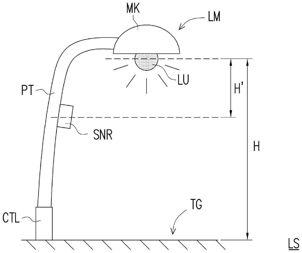
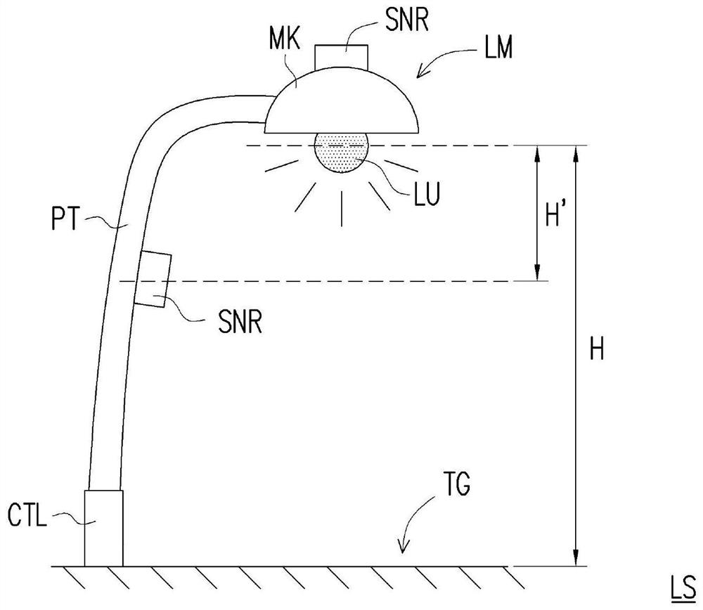
[0045] When there is sufficient illuminance value in the target lighting area of ​​the lighting system (hereinafter referred to as the expected illuminance value Lux ex ), it can be considered that the lighting system provides a good lighting effect. Therefore, in the lighting system and lighting method proposed by the present invention, when the ambient light source is sufficient, the lighting system does not provide or provide less light energy; when the ambient light source is insufficient, the lighting system will provide sufficient light energy to make the target The desired illuminance value is reached in the lighting area.

[0046] On the other hand, because the environmental visib...


PUM


Abstract

The invention provides a lighting system and a lighting method, the lighting system includes a light emitting module, an illuminance sensor and a controller. The light emitting module includes a light emitting unit, and the light emitting module can adjust the output power of the light emitting unit according to the control signal. The illuminance sensor can obtain the illuminance value. The controller is coupled to the light-emitting module and the illuminance sensor, and is adapted to generate a control signal for adjusting the light-emitting unit according to the value difference between the illuminance threshold and the obtained illuminance value, wherein the illuminance threshold is related to the difference between the light-emitting unit and the illuminance sensor Geometry sets the relationship. Accordingly, it is possible to save power and meet usage requirements.

Description

technical field [0001] The present invention relates to an illumination system and an illumination method, in particular to an illumination system and an illumination method that can adjust the brightness according to the environment. Background technique [0002] In the existing electronic devices for lighting, the user must manually control the switch or adjust the brightness according to his needs. [0003] Taking street lights as an example, the current common practice is to set the time points of turning on and off, so that the street lights can function at least after nightfall. However, the time of sunrise and sunset is not the same in different seasons, so the current practice may turn on the street lights when the sky is still bright and cause a waste of electricity, or turn on the street lights when the sky is already dark and cause road damage. poor vision. In addition, weather factors such as cloud thickness, rain, and smog will also affect visibility, which wi...

Claims


Application Information

Patent Timeline
Patent Type & Authority Patents(China)
IPC IPC(8): H05B47/11
CPCH05B47/11Y02B20/40
Inventor 高铭圳
Owner LEOTEK CORP
Why Eureka
Try Eureka