3D sensing technology based on multiple structured illumination

A structured, optical sensor technology for re-radiation of electromagnetic waves, image enhancement, distance measurement, etc.

Active Publication Date: 2019-04-23
SHENZHEN GOODIX TECH CO LTD
View PDF11 Cites 3 Cited by
  • Summary
  • Abstract
  • Description
  • Claims
  • Application Information

AI Technical Summary

Problems solved by technology

This limitation is unacceptable in some cases where a very small package (hardware) i...

Method used


Image

  • 3D sensing technology based on multiple structured illumination
  • 3D sensing technology based on multiple structured illumination
  • 3D sensing technology based on multiple structured illumination

Examples


Embodiment Construction

[0025] In the following description, various embodiments will be described. For purposes of illustration, specific configurations and details are set forth in order to provide a thorough understanding of the embodiments. It will also be apparent, however, to those skilled in the art that these embodiments may be practiced without these specific details. Furthermore, well-known features may be omitted or simplified in order not to obscure the described embodiments.

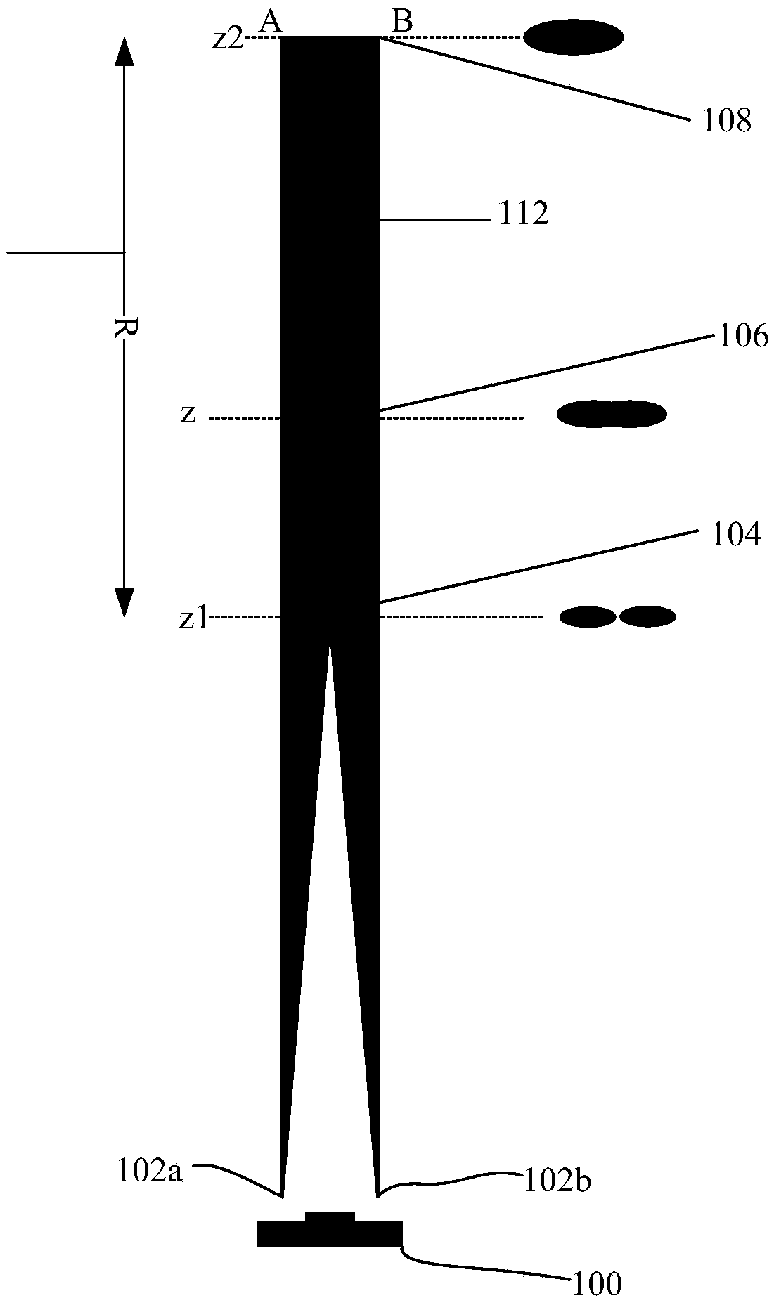
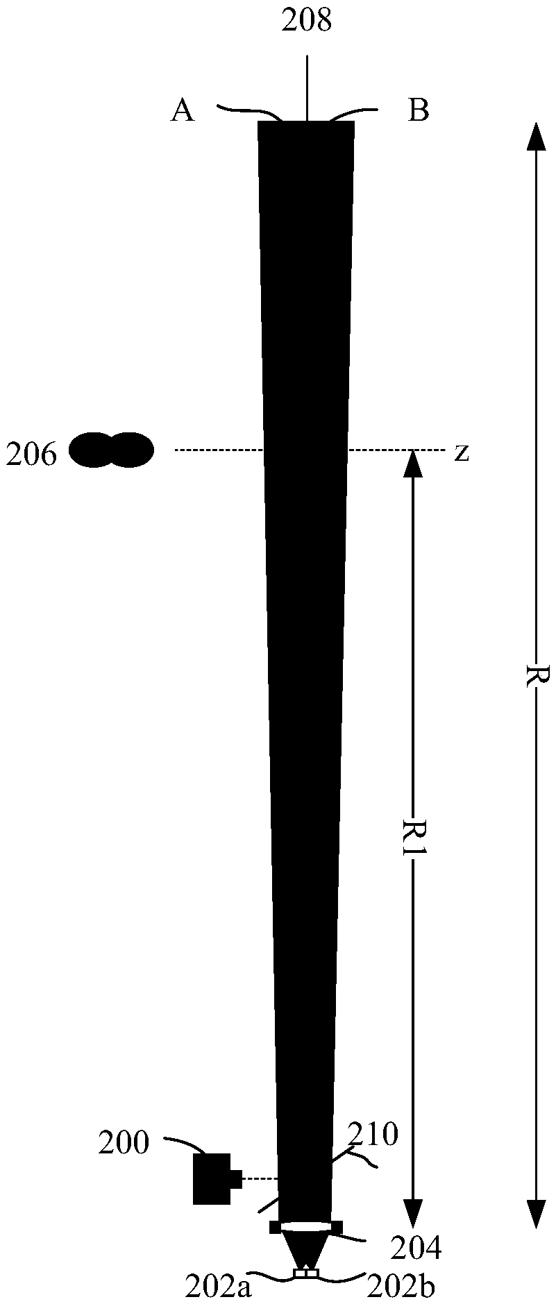
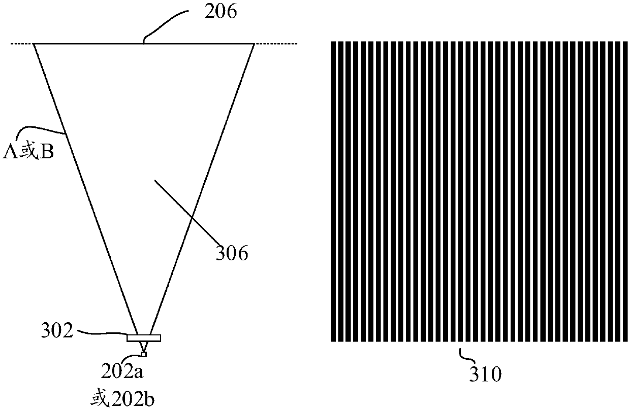
[0026] Various embodiments may facilitate measuring the distance of an object of interest. The object's distance can be determined by comparing two images of the object. When comparing images of an object, traditional triangulation methods typically require streaks or light patterns on that object observed at different locations. Unlike traditional triangulation methods, embodiments according to the present disclosure can obtain distance information by simply casting several rays on the object. In these embodim...


PUM


Abstract

A method and an apparatus for measuring a distance of an object. For achieving this, a first light source(102a, 202a) and a second light source(102b, 202b) can be configured to emit first light and asecond light toward the object to illuminate the object. The emission of the first light and second light can be configured such that the two lights converge at a first point and diverge at a second point. An optical sensor(100, 200, 700) can be used to capture a first image of the object illuminated by the first light, and capture a second image of the object illuminated by the second light. An image difference between the first image and the second image of the object can be determined. The distance of the object with respect to the first point can then be determined based on the image difference and a distance difference between the first point and the second point.

Description

[0001] Priority claims and cross-references to related applications [0002] This patent document claims priority to U.S. Provisional Patent Application Serial No. 15 / 675,779, entitled "3D Sensing Technology Based on Multi-Structured Illumination," filed August 13, 2017. technical field [0003] Embodiments herein relate generally to depth measurement methods for determining object distances. Background technique [0004] In 3D computer graphics, a depth map is an image or image channel that contains information related to the distance from the viewpoint to the surface of objects in the scene. There are many common known methods for determining depth maps. For example, time-of-flight (TOF) is known in the art and is used to measure the distance of an object relative to a reference point by emitting a light beam at the object. Typically, under TOF, a ray can be emitted towards the object at t1 and (due to reflection by the object) the returned ray can be captured at time t2...

Claims


Application Information

Patent Timeline
IPC IPC(8): G01S17/89
CPCG01S17/46G01S17/89G01S7/4815G01S7/493G01B11/026G06T7/586G06T7/521G06T2207/10152G06T2207/10024G06T7/194G01C3/08G01B11/22G06T2207/10004G06T2207/10028G06T2207/20224G01B11/25
Inventor 何毅皮波
Owner SHENZHEN GOODIX TECH CO LTD
Why Eureka
Try Eureka