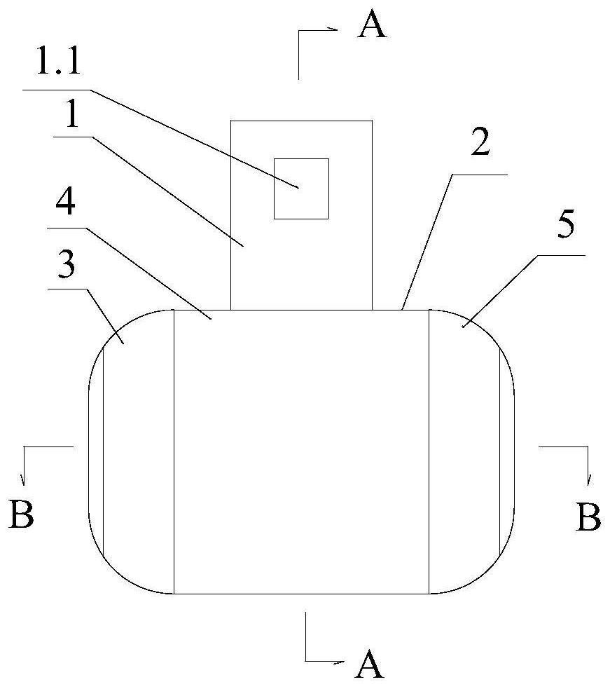
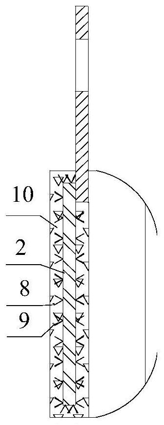
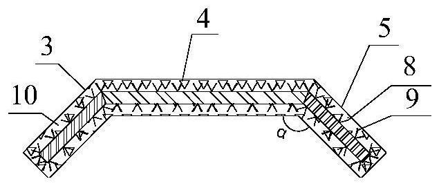
However, in the process of removing slag from molten iron in actual production, due to the adhesion between the dross and the molten iron and the driving force of the immersed part of the slag removal plate on the molten iron, the molten iron is also removed during the dross removal process. Therefore, the molten iron The problem of slag removal is unavoidable, and as the number of slag removal operations and the depth of slag removal board immersion in molten iron increase, the iron loss of slag removal continues to increase; due to the shape difference between the rectangular slag removal board and the circular section of the molten iron tank, the It is difficult to cover the scum in the edge and rear wall area; because the rectangular scum plate lacks the wrapping effect on the scum, the scum is easy to squeeze and overflow from both sides of the scum plate during the scum removal process; due to the high temperature oxidation of the steel slag plate And the high-temperature carburizing and melting in the molten iron, the lower part of the slag plate is easy to oxidize and melt, especially the center part of the bottom of the slag plate that has been in contact with the molten iron for the longest time, which often makes the bottom of the slag plate form a large upward protruding gap; Due to the relationship between the concave arc shape of the lower edge of the molten iron tank and the linear structure of the lower edge of the rectangular slag removal plate, when the scum is removed from the iron removal nozzle, there is a large gap between the lower edge of the slag removal plate and the iron removal nozzle, although it is convenient The molten iron flows back to the molten iron tank through the gap, but at the same time it also makes the scum flow back, and it is easy to cool and solidify during the reflux process, so that the iron slag and iron accumulate and block, which is not conducive to the removal of the scum during the second slag removal process, and forms Scattering, causing problems such as increased iron loss and scattered scum, resulting in frequent slag removal and repair of the iron nozzle; due to the above reasons, the number of slag removal operations of molten iron machinery is long, the slag removal time is long, the iron loss is large, Low efficiency of slag removal, short service life of slag removal board, high operating cost, etc. In addition, the adaptability of the structure size of the slag removal board and the size of the molten iron tank has not been studied in detail, and the design of the slag removal board mainly relies on empirical design, resulting in differences between different enterprises There are huge differences in the key technical indicators of hot metal slag removal
At the same time, due to factors such as the heavy weight of the slag removal board, the high-temperature deformation of the fixing mechanism, and the firm adhesion of the splashed slag and iron, it is difficult to replace the slag removal board and the operation takes a long time, which seriously affects the steelmaking production rhythm and restricts the technical and economic indicators of the pretreatment process. The improvement of steelmaking production efficiency and the play
[0003] In response to the above problems, domestic and foreign scholars have carried out a lot of work on how to improve the efficiency of molten iron mechanical slag removal, especially the slag removal plate that directly drives the scum movement. Various new types of slag removal boards have been invented from the perspectives of longevity of the slag board and reduction of slag removal iron loss. The spherical surface and the bottom surface are cast steel slag removal plates with convex arc surface structure, which increases the scum containment capacity of the slag removal board and the slag removal capacity of a single slag removal operation, and reduces the bottom surface of the slag removal board and the bottom of the molten iron tank. The gap on the concave surface prevents the solidification and accumulation of scum and molten iron in the iron nozzle during the reflux process. At the same time, dip-coat graphite paint on the surface of the slag removal plate to reduce the adhesion of slag and iron on the slag removal board and reduce the oxidation and ablation of the slag removal board. The purpose of prolonging the service life of the slag removal plate, but in actual production and application, due to the difficulty in effectively implementing the graphite coating on the surface of the slag removal board, the adhesion of slag and iron to the slag removal board and oxidative melting loss are still serious, resulting in difficult convex structures with limited scale. Maintained, and failed to promote the application due to production cost issues
The Chinese patent "A new type of hot metal slag removal board, authorized announcement number CN201807734U" discloses a cast steel slag removal board whose front, back and bottom surfaces are arc-shaped, and the slag removal is realized by arranging a gas cooling channel inside the slag removal board The on-line cooling of the slag stripper during the process can reduce the high temperature oxidation and corrosion of the slag stripper and achieve the purpose of prolonging the life of the slag stripper. Once the cooling channel of the slag removal plate is ablated, it must be replaced, which will affect the production rhythm
The above three patents all take the measure of covering the surface of the metal main board with a refractory material layer to realize the high temperature protection of the refractory material layer for the metal main board. However, how to ensure the structural stability of the refractory material layer during use and realize the protection of the refractory material layer against The reliable protection of the metal main board has not been explained, especially the internal stress problem of the metal main board and the refractory material layer due to different materials. If it is not solved properly, it will inevitably lead to damage to the refractory layer of the slag removal board. During the slag removal process, the slag removal board and the molten iron tank The visual error of the relative positional relationship leads to difficult operation, a sharp drop in slag removal efficiency, and even damage to the slag removal plate and the molten iron tank wall; in addition, the design of the iron overflow hole on the slag removal board and the molten iron return comb teeth structure design, although theoretical The reflux of molten iron in the slag removal plate can be realized on the surface, but the serious sticky slag and iron in the slag removal process make it difficult for the molten iron return channel to be smooth. At the same time, the lower comb structure greatly reduces the wear resistance of the slag removal board, resulting The shape matching between the plate and the molten iron tank will decrease, and the slag removal efficiency will be further reduced
At the same time, at present, domestic iron and steel enterprises have not yet treated molten iron slag removal as a core key technology. The influence of the structural size matching relationship between the slag strippers on the operation rules of molten iron and dross has not been systematically studied, which is the main reason why the above core content cannot be actually implemented in the relevant patents and literature materials, but only the slag strippers are involved
[0004] To sum up, although a lot of explorations have been carried out in the aspects of slag stripping structure, slag stripping plate composition and slag stripping plate preparation materials, the improvement and development direction of hot metal slag stripping has been proposed, and a series of improvement measures have been formulated, but the relevant improvement measures There is still a big gap from the actual production requirements, and it still needs to be continuously improved and upgraded from the actual production


