Minitype piezoelectric pump based on optical transmission welding, piezoelectric pump unit and assembling method
A technology of optical transmission and assembly method, which is applied to the parts of pumping devices for elastic fluids, pump devices, pumps with flexible working elements, etc. and other problems, to achieve the effect of simplifying processing difficulty, reducing equipment investment, simplifying structure and assembly process
- Summary
- Abstract
- Description
- Claims
- Application Information
AI Technical Summary
Problems solved by technology
Method used
Image

Examples
Embodiment 1
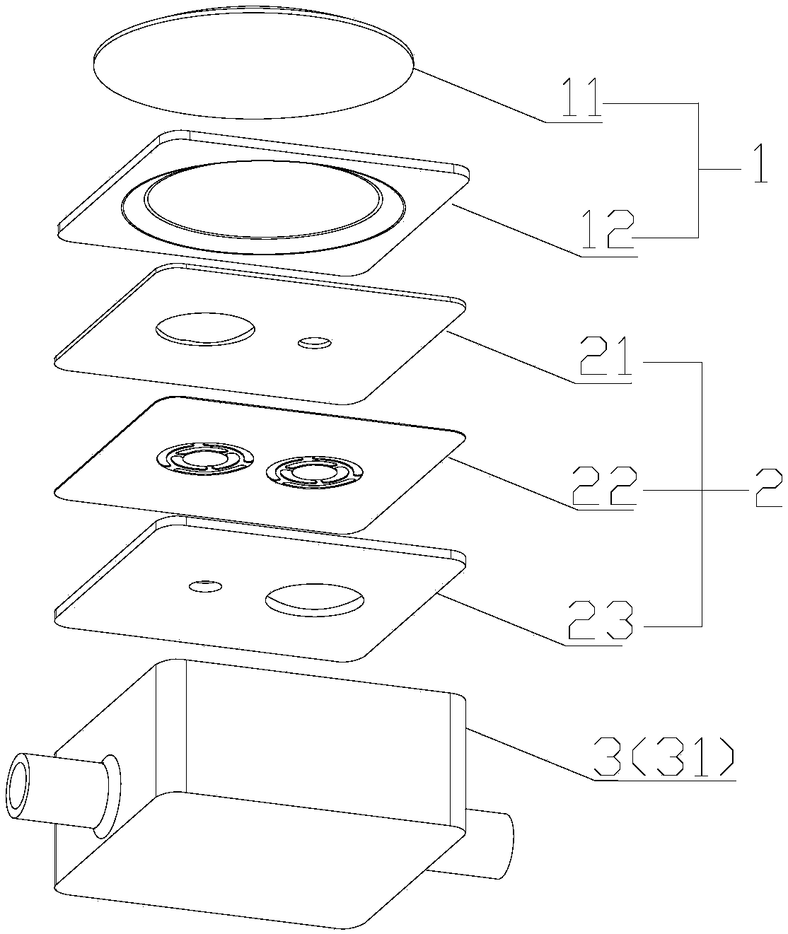
[0072] Such as Figure 1-2 As shown in 11-14, this embodiment provides a miniature piezoelectric pump based on optical transmission welding, which includes an excitation unit 1, a valve body unit 2, and a valve seat unit 3 that are sequentially stacked from top to bottom.
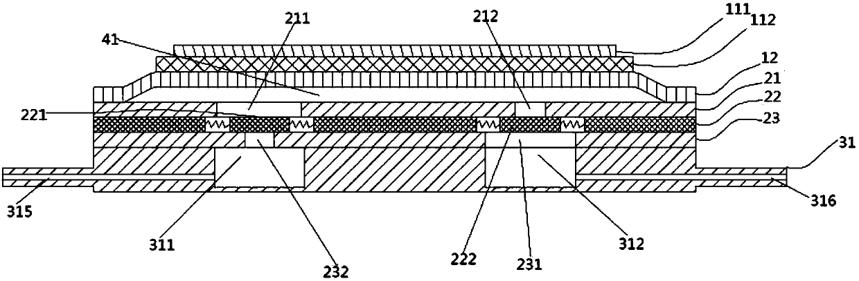
[0073] The excitation unit 1 provides a driving force for the piezoelectric pump. The excitation unit 1 includes the piezoelectric vibrator 11 and the cavity diaphragm 12, and the piezoelectric vibrator 11 is arranged on the upper surface of the cavity diaphragm 12 and in the center. Alignment settings. The piezoelectric vibrator 11 includes a piezoelectric ceramic 111 and a piezoelectric vibrator substrate 112, and the piezoelectric ceramic 111 is arranged on the upper surface of the piezoelectric vibrator substrate 112 and aligned with the center. A pump cavity 41 with a certain accommodation space is formed between the upper surface of the valve body unit 2 and the lower surface of the excitation unit. Pre...
Embodiment 2
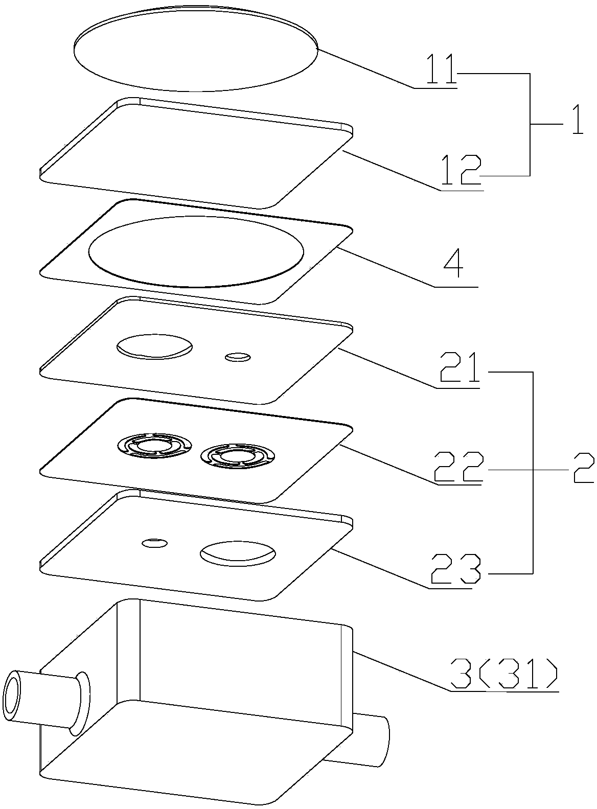
[0087] Such as Figure 3-4 As shown in 11-14, the structure of the miniature piezoelectric pump in this embodiment and the first embodiment is basically the same. The only difference is that the miniature piezoelectric pump in this embodiment also includes a cavity diaphragm 4, which is provided with Between the cavity diaphragm 12 and the upper valve plate pressing plate 21. The cavity diaphragm 4 is provided with a through hole, and the cavity diaphragm 12, the cavity diaphragm 4 and the upper valve plate pressing plate 21 together form a pump cavity 41. Preferably, the cavity diaphragm 4 may have a planar structure, and no sinking structure is required on its outer periphery, which is convenient for processing.
[0088] In this embodiment of the miniature piezoelectric pump based on optical transmission welding, its component parts, the cavity diaphragm 12, the valve body unit 2, the valve seat unit 3, and the cavity diaphragm 4 are all made of thermoplastic, such as PP, PC, P...
Embodiment 3
[0098] Such as Figure 5-8 As shown in 11-14, the structure of the miniature piezoelectric pump in this embodiment and the second embodiment is basically the same, and the difference lies in the structure of the valve seat unit.
[0099] The valve seat unit 3 includes an upper valve seat diaphragm 32, a valve seat 31, a lower valve seat diaphragm 33, and a bottom plate 34. The upper valve seat diaphragm 32, the valve seat 31, the lower valve seat diaphragm 33 and the bottom plate 34 are arranged from top to bottom. Stack in turn. The upper valve seat diaphragm 32 is provided with a first flow hole 321 and a second flow hole 322 with the same inner diameter. The valve seat 31 is provided with a third flow hole 313 communicating with the inlet sink cavity 311 and The fourth flow hole 314 communicating with the outlet flow chamber 312, the inner diameter of the third flow hole 313 and the fourth flow hole 314 are equal, the inner diameters of the inlet flow chamber 311 and the outle...
PUM
 Abstract
Description
Claims
Application Information
 - R&D Engineer
- R&D Manager
- IP Professional
- Industry Leading Data Capabilities
- Powerful AI technology
- Patent DNA Extraction
Browse by: Latest US Patents, China's latest patents, Technical Efficacy Thesaurus, Application Domain, Technology Topic.
© 2024 PatSnap. All rights reserved.Legal|Privacy policy|Modern Slavery Act Transparency Statement|Sitemap