An air conditioner indoor unit

An air-conditioning indoor unit and inner surface technology, applied in air-conditioning systems, space heating and ventilation, heating methods, etc., can solve the problems of low contribution value, low fin sound energy, large air volume, etc., to reduce BPF noise, The effect of reducing energy concentration

Active Publication Date: 2021-04-16
QINGDAO HISENSE HITACHI AIR CONDITIONING SYST
View PDF6 Cites 0 Cited by
  • Summary
  • Abstract
  • Description
  • Claims
  • Application Information

AI Technical Summary

Problems solved by technology

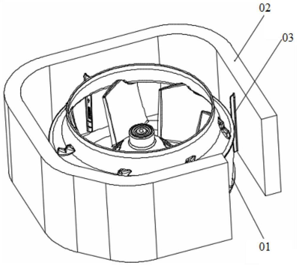
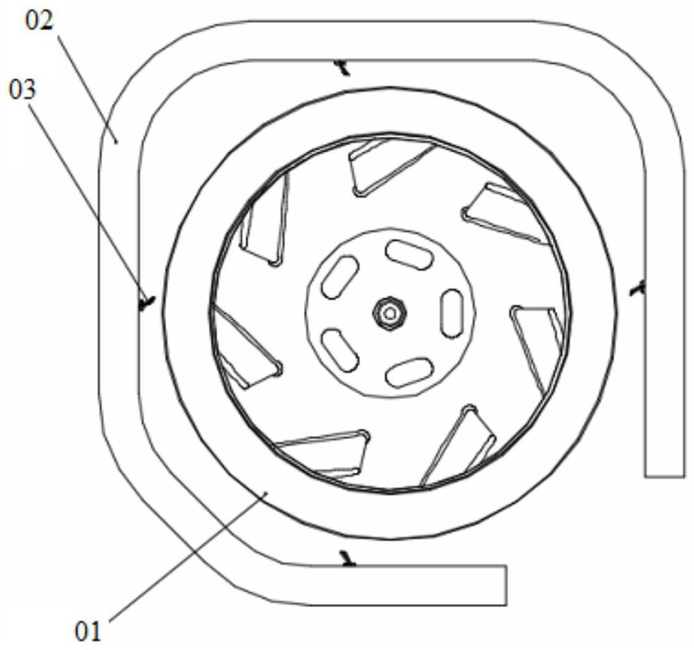
[0003] Existing commercial air conditioner indoor units (four-direction / two-direction / one-direction series) all use the backward centrifugal fan 01 as the air supply fan. The larger air volume and lower noise can be obtained, but since this series of models all use the design of heat exchanger 02 surrounding the fan (refer to figure 1 and figure 2 ), this design will cause the tangential velocity of the airflow passing through the inner surface of the heat exchanger 02 to approach the maximum when the fan rotates to the closest point of the heat exchanger 02, and the airflow interacts with the fins of the heat exchanger 02 to cause the heat exchanger 02 to generate Fin sound (high-frequency howling sound 3000Hz~5000Hz)
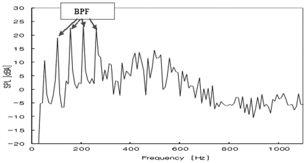
[0004] The energy of the finned sound is low in the high-frequency range, and its contribution to the noise is low or negligible, but the finned sound will cause great trouble to the user's comfort experience, so the general design of products in the industry will increase the diversion Plate 03 is used to change the wind direction to eliminate fin noise, but using this design is equivalent to adding a vortex structure to the fan. Due to the existence of the deflector 03 similar to the vortex tongue, the interaction between the fan and the deflector 03 will produce a very obvious BPF ( Fan frequency frequency / rotation noise) noise (refer to image 3 ), the rotation noise is also the main noise source when the indoor unit of the air conditioner is working

Method used


Image

  • An air conditioner indoor unit
  • An air conditioner indoor unit
  • An air conditioner indoor unit

Examples


Embodiment Construction

[0020]Next, the technical solutions in the embodiments of the present invention will be described in the following examples, which will be described, and it is clear that the described embodiments are merely embodiments of the present invention, rather than a full segment embodiment. . Based on the embodiments of the present invention, there are all other embodiments obtained without making creative labor without making creative labor premises.

[0021]In the description of the invention, it is to be understood that the terms "center", "upper", "under",

[0022]"Before", "After", "Left", "Right", "Right", "Level", "Top",

[0023]The orientation or position of "bottom", "inside", "outside", etc. is based on the orientation or positional relationship shown in the drawings, is merely description of the present invention and simplified description, rather than indicating or implying means of means Or elements must have specific orientation, constructed and operated in a particular direction, and...


PUM


Abstract

The invention discloses an air conditioner indoor unit, which relates to the technical field of air conditioners, which can eliminate fin sound and at the same time weaken BPF noise. The air conditioner indoor unit of the present invention includes a centrifugal fan and a heat exchanger arranged outside the centrifugal fan. A baffle plate is provided on the inner surface of the heat exchanger near the centrifugal fan, and the baffle plate is connected to the centrifugal fan. The relative positions of the bottoms of the centrifugal fans are concave and / or offset in a direction away from the centrifugal fan. The present invention is used to regulate indoor air.

Description

Technical field[0001]The present invention relates to the field of air conditioning, and more particularly to an air conditioning indoor unit.Background technique[0002]Air conditioning indoor air-conditioning noise has been attached to consumers, so air-conditioning equipment manufacturers are constantly proposing technical improvements.[0003]The existing commercial air conditioner (four-direction / two-direction / one direction series) is used to use the centrifugal fan 01 as a blow sail fan, and the advantage is that the rear centrifugal fan 01 is relatively easy in the lower speed and no volute. Get larger air volume and low noise, but because this series of models use heat exchanger 02 surrounded by fans (referencefigure 1 withfigure 2 This design can cause the fan to rotate to the heat exchanger 02, when the airflow tangent speed in the inner surface of the heat exchanger 02 is close to the maximum value, the gas stream is interacting with the fin interaction of the heat exchan...

Claims


Application Information

Patent Timeline
Patent Type & Authority Patents(China)
IPC IPC(8): F24F1/0022F24F13/10F24F13/24
CPCF24F1/0022F24F13/10F24F13/24
Inventor 颜鲁华徐坤宋旭彤林忠超
Owner QINGDAO HISENSE HITACHI AIR CONDITIONING SYST
Why Eureka
Try Eureka