Optical imaging lens
An optical imaging lens and lens technology, applied in optics, optical components, instruments, etc., can solve the problem of poor performance of lens imaging quality and detail.
- Summary
- Abstract
- Description
- Claims
- Application Information
AI Technical Summary
Problems solved by technology
Method used
Image
Examples
Embodiment 1
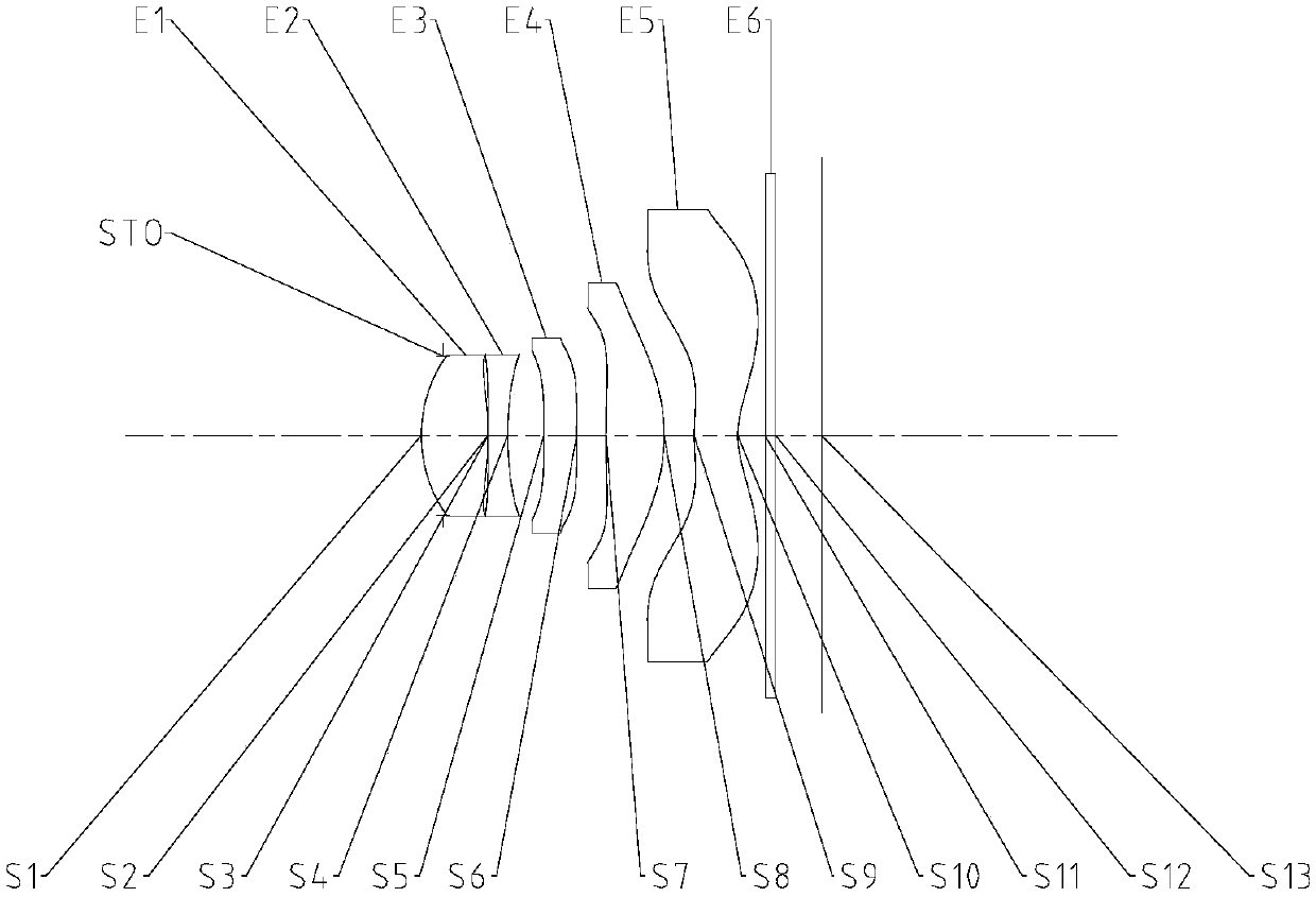
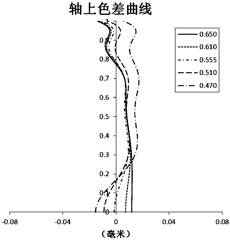
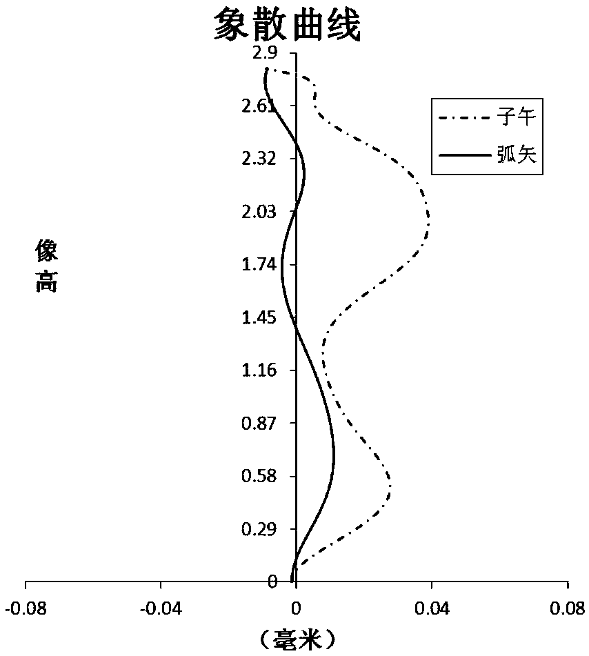
[0077] Refer to the following Figure 1 to Figure 2D An optical imaging lens according to Embodiment 1 of the present application is described. figure 1 A schematic structural diagram of an optical imaging lens according to Embodiment 1 of the present application is shown.
[0078] Such as figure 1 As shown, the optical imaging lens according to the exemplary embodiment of the present application includes sequentially along the optical axis from the object side to the image side: a stop STO, a first lens E1, a second lens E2, a third lens E3, and a fourth lens E4 , the fifth lens E5, the filter E6 and the imaging surface S13.
[0079]The first lens E1 has positive refractive power, its object side S1 is convex, and its image side S2 is concave. The second lens E2 has negative refractive power, its object side S3 is convex, and its image side S4 is concave. The third lens E3 has negative refractive power, its object side S5 is convex, and its image side S6 is concave. The ...
Embodiment 2
[0109] Refer to the following Figure 3 to Figure 4D An optical imaging lens according to Embodiment 2 of the present application is described. In this embodiment and the following embodiments, for the sake of brevity, descriptions similar to those in Embodiment 1 will be omitted. image 3 A schematic structural diagram of an optical imaging lens according to Embodiment 2 of the present application is shown.
[0110] Such as image 3 As shown, the optical imaging lens according to the exemplary embodiment of the present application includes sequentially along the optical axis from the object side to the image side: a stop STO, a first lens E1, a second lens E2, a third lens E3, and a fourth lens E4 , the fifth lens E5, the filter E6 and the imaging surface S13.
[0111] The first lens E1 has positive refractive power, its object side S1 is convex, and its image side S2 is concave. The second lens E2 has negative refractive power, its object side S3 is convex, and its image...
Embodiment 3
[0125] Refer to the following Figure 5 to Figure 6D An optical imaging lens according to Embodiment 3 of the present application is described. Figure 5 A schematic structural diagram of an optical imaging lens according to Embodiment 3 of the present application is shown.
[0126] Such as Figure 5 As shown, the optical imaging lens according to the exemplary embodiment of the present application includes sequentially along the optical axis from the object side to the image side: a stop STO, a first lens E1, a second lens E2, a third lens E3, and a fourth lens E4 , the fifth lens E5, the filter E6 and the imaging surface S12.
[0127] The first lens E1 has positive refractive power, its object side S1 is convex, and its image side S2 is convex. The second lens E2 has negative refractive power, its object side S2 is concave, and its image side S3 is concave. In this embodiment, the image side S2 of the first lens E1 is substantially coincident with the object side S2 of t...
PUM
| Property | Measurement | Unit |
|---|---|---|
| Full field of view | aaaaa | aaaaa |
Abstract
Description
Claims
Application Information
 - R&D Engineer
- R&D Manager
- IP Professional
- Industry Leading Data Capabilities
- Powerful AI technology
- Patent DNA Extraction
Browse by: Latest US Patents, China's latest patents, Technical Efficacy Thesaurus, Application Domain, Technology Topic.
© 2024 PatSnap. All rights reserved.Legal|Privacy policy|Modern Slavery Act Transparency Statement|Sitemap


