Cutter assembly and food processor

A technology for a food processor and a knife assembly, which is applied in the field of food processors, can solve the problem that the knife and the knife shaft are difficult to take into account the convenience of disassembly and assembly, safety and reliability, etc., and achieve the effect of simple and convenient disassembly operation and deepening of the depth.

Active Publication Date: 2019-05-03
GUANGDONG MIDEA CONSUMER ELECTRICS MFG CO LTD
View PDF10 Cites 1 Cited by
  • Summary
  • Abstract
  • Description
  • Claims
  • Application Information

AI Technical Summary

Problems solved by technology

[0004] The first object of the present invention is to provide a knife assembly, which aims to solve the technical problem that the connection between the knife and the knife shaft in the existing food cooking is difficult to take into account the convenience of disassembly and assembly, safety and reliability

Method used


Image

  • Cutter assembly and food processor
  • Cutter assembly and food processor
  • Cutter assembly and food processor

Examples


Embodiment 1

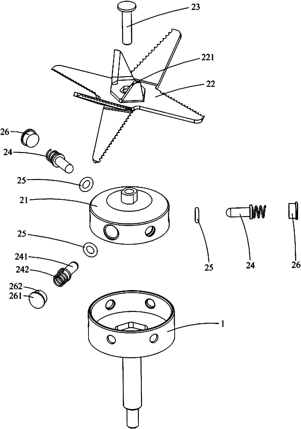
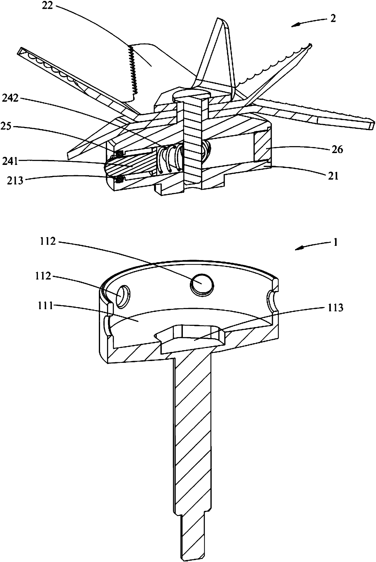
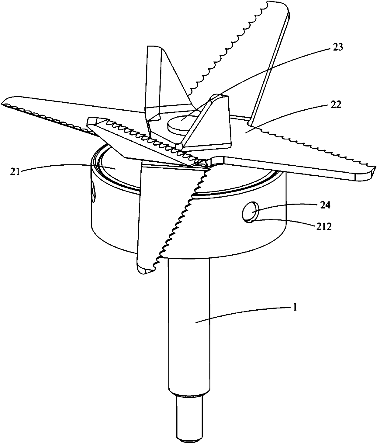
[0059] Such as Figure 1-9 As shown, the knife assembly 100 provided by Embodiment 1 of the present invention is used in a food cooking machine, and it includes a knife shaft 1 and a knife 2 detachably mounted on the knife shaft 1. The top of the knife shaft 1 is provided with a concave cavity 111, and the concave cavity The side wall of the cavity 111 is provided with a positioning hole 112; the tool 2 includes a base 21, a blade 22, a locking positioning member 23 and an elastic member 24, the base 21 is accommodated and positioned in the cavity 111, and the blade 22 is placed on the base 21, the locking positioning member 23 passes through the connecting base 21 vertically and locks the blade 22 on the base 21. The elastic member 24 includes one end disposed in the base 21 and the other end extending out of the base 21 laterally. The positioning rod 241 and the two ends inserted in the positioning hole 112 are respectively abutted against the positioning rod 241 and the fir...

Embodiment 2

[0095] The main difference between the cutter assembly 100 and the food cooking machine provided in this embodiment and the first embodiment is that the elastic member 24 is set differently, which is specifically reflected in: Figure 1-9 As shown, in Embodiment 1, the elastic member 24 only includes one elastic piece; Figure 10-12 As shown, the elastic member 24 in this embodiment includes two elastic pieces. Specifically, in this embodiment, the elastic member 24 further includes a second elastic member 243 sheathed on the rod body 2411, one end of the second elastic member 243 abuts against the convex cap 2412, and the other end abuts against the shoulder 213. . In this embodiment, when the cutter assembly 100 is rotating, the positioning rod 241 can overcome the elastic force of the second elastic member 243 under the action of centrifugal force to compress the second elastic member 243 and protrude outward to increase the depth inserted into the positioning hole 112 an...

Embodiment 3

[0106] The main difference between the cutter assembly 100 and the food cooking machine provided in this embodiment and the first and second embodiments is that the setting of the locking and positioning member 23 is different, which is specifically reflected in: Figure 1-12 As shown, in Embodiment 1 and Embodiment 2, the locking and positioning member 23 is integrally manufactured into a molding structure; and as Figure 13-14 As shown, in this embodiment, the locking and positioning member 23 is a separate manufacturing and forming structure. Specifically, in this embodiment, the locking positioning member 23 includes a first screw 231 passing through the blade 22 and passing through the connecting base 21 from the top of the base 21 and a second screw 231 passing through the connecting base 21 from the bottom of the base 21. One end of the elastic member 24 abuts against the second screw 232 . In this embodiment, the first screw 231 is used to lock the blade 22 on the bas...


PUM


Abstract

The invention is applicable to the field of household electric appliances, and discloses a cutter assembly and a food processor. The cutter assembly comprises a cutter shaft and a cutter detachably mounted on the cutter shaft, wherein a concave cavity is arranged in the top of the cutter shaft, and positioning holes are arranged in the side wall of the concave cavity; the cutter comprises a base,a blade, a locking positioning component and elastic components, the base is accommodated and positioned in the concave cavity, the locking positioning component is connected with the blade and the base in a penetrating manner along the vertical direction, each elastic component comprises a positioning rod with one end arranged in the base and the other end horizontally extending out of the base and inserted in the corresponding positioning hole, and a first elastic part with two ends butted to the positioning rod and the locking positioning component, and the end face, far away from each first elastic part, of the corresponding positioning rod is an inclined face or an arc face. When the cutter assembly rotates, under the effect of the centrifugal force, the positioning rods further extend out from the base and are inserted into the positioning holes, so that the phenomenon that the base slides from the concave cavity and flies out is avoided, thus the stable reliability when the cutter is mounted on the cutter shaft is guaranteed, and in addition, the mounting and dismounting of the cutter and the cutter shaft are convenient.

Description

technical field [0001] The invention relates to the field of household electrical appliances, in particular to a cutter assembly and a food cooking machine with the cutter assembly. Background technique [0002] A food cooking machine generally includes a base assembly, a cup assembly and a knife assembly. The cup assembly is placed on the base assembly. The knife assembly has a knife located in the cup assembly and a knife shaft that is connected to the base assembly and the knife by transmission. In the traditional technology, the cutter assembly is fixed on the chassis of the cup body assembly, and the cutter assembly cannot be disassembled or is not easily disassembled. In this way, during the specific use of the food processor, when the bottom of the food occurs, the cutter and the chassis It is very difficult to clean the food processing machine, which will cause dead ends in the food processing machine, which seriously affects the hygienic reliability of the product u...

Claims


Application Information

Patent Timeline
Patent Type & Authority Applications(China)
IPC IPC(8): A47J43/07
Inventor 招绍坤刘云祥唐燕
Owner GUANGDONG MIDEA CONSUMER ELECTRICS MFG CO LTD
Why Eureka
Try Eureka