Knife components and food processors
A cutting tool assembly and cutting tool technology, applied in the field of food cooking machines, can solve the problem that the cutting tool and the cutting shaft are difficult to take into account the convenience of disassembly and assembly, safety and reliability, etc., and achieve the effect of simple and convenient disassembly operation and deepening the depth
- Summary
- Abstract
- Description
- Claims
- Application Information
AI Technical Summary
Problems solved by technology
Method used
Image
Examples
Embodiment 1
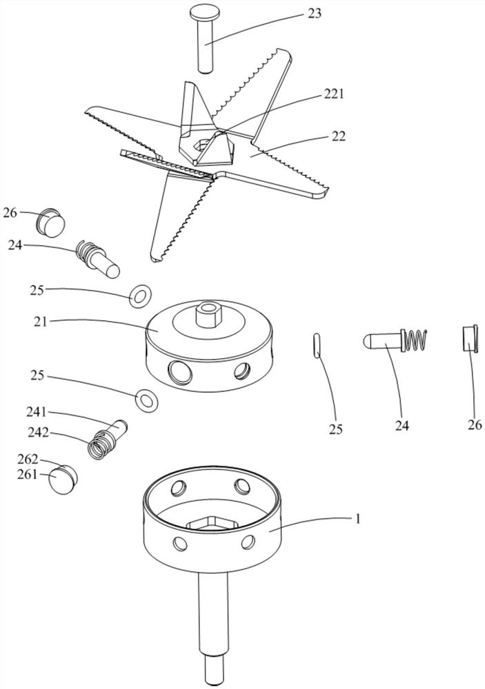
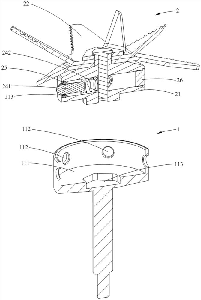
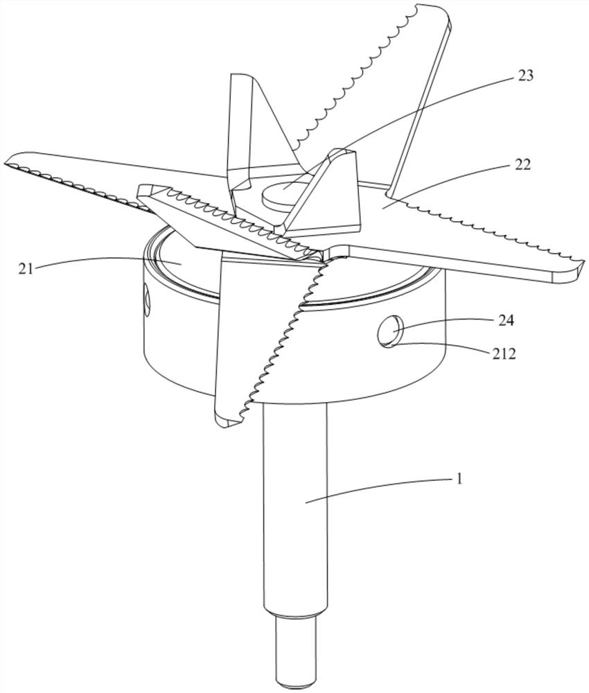
[0059] Such as Figure 1-9 As shown, the knife assembly 100 provided by Embodiment 1 of the present invention is used in a food cooking machine, and it includes a knife shaft 1 and a knife 2 detachably mounted on the knife shaft 1. The top of the knife shaft 1 is provided with a concave cavity 111, and the concave cavity The side wall of the cavity 111 is provided with a positioning hole 112; the tool 2 includes a base 21, a blade 22, a locking positioning member 23 and an elastic member 24, the base 21 is accommodated and positioned in the cavity 111, and the blade 22 is placed on the base 21, the locking positioning member 23 passes through the connecting base 21 vertically and locks the blade 22 on the base 21. The elastic member 24 includes one end disposed in the base 21 and the other end extending out of the base 21 laterally. The positioning rod 241 and the two ends inserted in the positioning hole 112 are respectively abutted against the positioning rod 241 and the fir...
Embodiment 2
[0095] The main difference between the cutter assembly 100 and the food cooking machine provided in this embodiment and the first embodiment is that the elastic member 24 is set differently, which is specifically reflected in: Figure 1-9 As shown, in Embodiment 1, the elastic member 24 only includes one elastic piece; Figure 10-12 As shown, the elastic member 24 in this embodiment includes two elastic pieces. Specifically, in this embodiment, the elastic member 24 further includes a second elastic member 243 sheathed on the rod body 2411, one end of the second elastic member 243 abuts against the convex cap 2412, and the other end abuts against the shoulder 213. . In this embodiment, when the cutter assembly 100 is rotating, the positioning rod 241 can overcome the elastic force of the second elastic member 243 under the action of centrifugal force to compress the second elastic member 243 and protrude outward to increase the depth inserted into the positioning hole 112 an...
Embodiment 3
[0106] The main difference between the cutter assembly 100 and the food cooking machine provided in this embodiment and the first and second embodiments is that the setting of the locking and positioning member 23 is different, which is specifically reflected in: Figure 1-12 As shown, in Embodiment 1 and Embodiment 2, the locking and positioning member 23 is integrally manufactured into a molding structure; and as Figure 13-14 As shown, in this embodiment, the locking and positioning member 23 is a separate manufacturing and forming structure. Specifically, in this embodiment, the locking positioning member 23 includes a first screw 231 passing through the blade 22 and passing through the connecting base 21 from the top of the base 21 and a second screw 231 passing through the connecting base 21 from the bottom of the base 21. One end of the elastic member 24 abuts against the second screw 232 . In this embodiment, the first screw 231 is used to lock the blade 22 on the bas...
PUM
 Abstract
Description
Claims
Application Information
 - R&D
- Intellectual Property
- Life Sciences
- Materials
- Tech Scout
- Unparalleled Data Quality
- Higher Quality Content
- 60% Fewer Hallucinations
Browse by: Latest US Patents, China's latest patents, Technical Efficacy Thesaurus, Application Domain, Technology Topic, Popular Technical Reports.
© 2025 PatSnap. All rights reserved.Legal|Privacy policy|Modern Slavery Act Transparency Statement|Sitemap|About US| Contact US: help@patsnap.com


