Quickly-assembled motorized floating barge and assembling method

A barge and maneuvering technology, applied to barges/flat-bottomed boats, ships, etc., can solve the problems of inflexible movement and single working conditions, and achieve the effects of reducing slapping, reliable connection, and flexible disassembly

Active Publication Date: 2021-06-11
CHINA SHIP SCIENTIFIC RESEARCH CENTER (THE 702 INSTITUTE OF CHINA SHIPBUILDING INDUSTRY CORPORATION)
View PDF11 Cites 0 Cited by
  • Summary
  • Abstract
  • Description
  • Claims
  • Application Information

AI Technical Summary

Problems solved by technology

[0002] The common floating wharf is generally composed of barges connected to the approach bridge on the shore. Its fixed structure determines that its working conditions are relatively single. It can only be used as a fixed wharf on the shore, and cannot be flexibly moved according to the needs of the task.

Method used


Image

  • Quickly-assembled motorized floating barge and assembling method
  • Quickly-assembled motorized floating barge and assembling method
  • Quickly-assembled motorized floating barge and assembling method

Examples


Embodiment Construction

[0029] The specific implementation manner of the present invention will be described below in conjunction with the accompanying drawings.

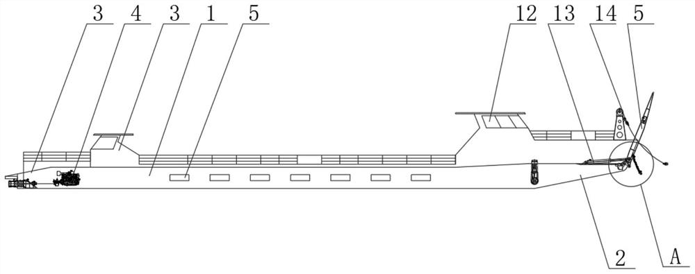
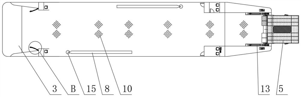
[0030] Such as Figure 1-Figure 4 As shown, the rapidly assembled mobile floating barge of this embodiment includes a barge body 1, the bow of the barge body 1 is provided with a wave splitting bow 2, and the tail of the barge body 1 is provided with a stern slide 3, and the wave splitting bow 2 and the stern The slideway 3 is matched and connected; the barge body 1 is provided with a power system 4 near the stern slideway 3, and the bow and stern of the barge body 1 are respectively provided with a cab and a control room 12,

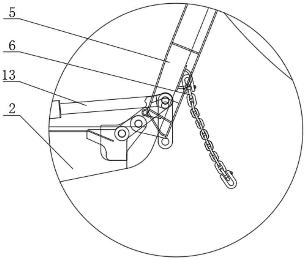
[0031] The wave splitting bow 2 is located at the bottom of the bow of the barge body 1, and the advancing direction end of the wave splitting bow 2 is rotatably connected with the bow ramp 5, and the bow ramp 5 is correspondingly provided with bow limit hinges 6,

[0032] The stern slideway 3 is located at the top...


PUM


Abstract

The invention relates to a quickly-assembled motorized floating barge which comprises a barge body, a wave dividing bow is arranged at the head of the barge body, a stern slideway is arranged at the tail of the barge body, and the wave dividing bow is connected with the stern slideway in a matched mode. A power system is arranged at the position, close to the stern slideway, of the barge body, the bow and the stern of the barge body are provided with a cab and a control cabin respectively, the wave dividing bow is located at the bottom of the bow of the barge body, the advancing direction end of the wave dividing bow is rotationally connected with a bow springboard, and head limiting hinges are correspondingly arranged on the two sides of the bow springboard. The stern slideway is arranged at top of the stern of the barge body. The stern chute is obliquely arranged; the two sides of the stern chute are arranged to be of a horn mouth structure outwards opened towards the two sides of the stern, and the horn mouth structure is matched with the outline of the bow of the barge body. Two sides of the stern chute are correspondingly provided with tail spacing hinges. According to the barge, the lap joint mode that every two barge bodies collide with each other is adopted, the front barge body and the rear barge body are not prone to swinging in the longitudinal direction through limiting of a horn mouth structure, reliable connection is achieved through the hinges, and transverse limiting is achieved through the positioning piles.

Description

technical field [0001] The invention relates to the technical field of motorized barges, in particular to a rapidly assembled motorized floating barge and an assembly method. Background technique [0002] The common floating wharf is generally composed of barges connected to the approach bridge on the shore. Its fixed structure determines that its working conditions are relatively single. It can only be used as a fixed wharf on the shore, and cannot be flexibly moved according to the task needs. For the temporary berthing of ships at specific locations, this form of floating wharf is not suitable. Contents of the invention [0003] Aiming at the shortcomings in the above-mentioned existing production technology, the applicant provides a fast-assembled motorized floating barge with a reasonable structure and an assembly method. The barges can be quickly connected in pairs and assembled to form a flexible floating wharf. At the same time, the barge It has the ability to loc...

Claims


Application Information

Patent Timeline
Patent Type & Authority Applications(China)
IPC IPC(8): B63B35/28B63B73/00
CPCB63B35/28B63B73/00Y02A10/11Y02T70/10
Inventor 眭爱国倪其军潘建强蒋一蒋昌师
Owner CHINA SHIP SCIENTIFIC RESEARCH CENTER (THE 702 INSTITUTE OF CHINA SHIPBUILDING INDUSTRY CORPORATION)
Why Eureka
Try Eureka