A new type of rainwater diversion well in sponge city

A technology of sponge city and diversion well, applied in the field of new large and small rainwater diversion wells in sponge city, can solve the problems of planting soil washing away, excessive water volume, yellowing of plant leaves, etc., to ensure normal use, improve filtering effect, and facilitate cleaning Effect

Active Publication Date: 2022-07-05
ZHONGYIFENG CONSTR GRP
View PDF5 Cites 0 Cited by
  • Summary
  • Abstract
  • Description
  • Claims
  • Application Information

AI Technical Summary

Problems solved by technology

[0004] This diversion well has the following obvious shortcomings: in heavy rain or continuous light rain, a large amount of rainwater will be transported and irrigated the plants, and most of the plants are planted outdoors. The plant itself and the planting soil have absorbed a lot of water. At this time, the rainwater transported through the water storage pipe will cause too much water, which will easily cause the leaves of the plants to turn yellow or directly wash away part of the planting soil.

Method used


Image

  • A new type of rainwater diversion well in sponge city
  • A new type of rainwater diversion well in sponge city
  • A new type of rainwater diversion well in sponge city

Examples


Embodiment 1

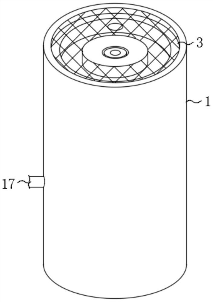
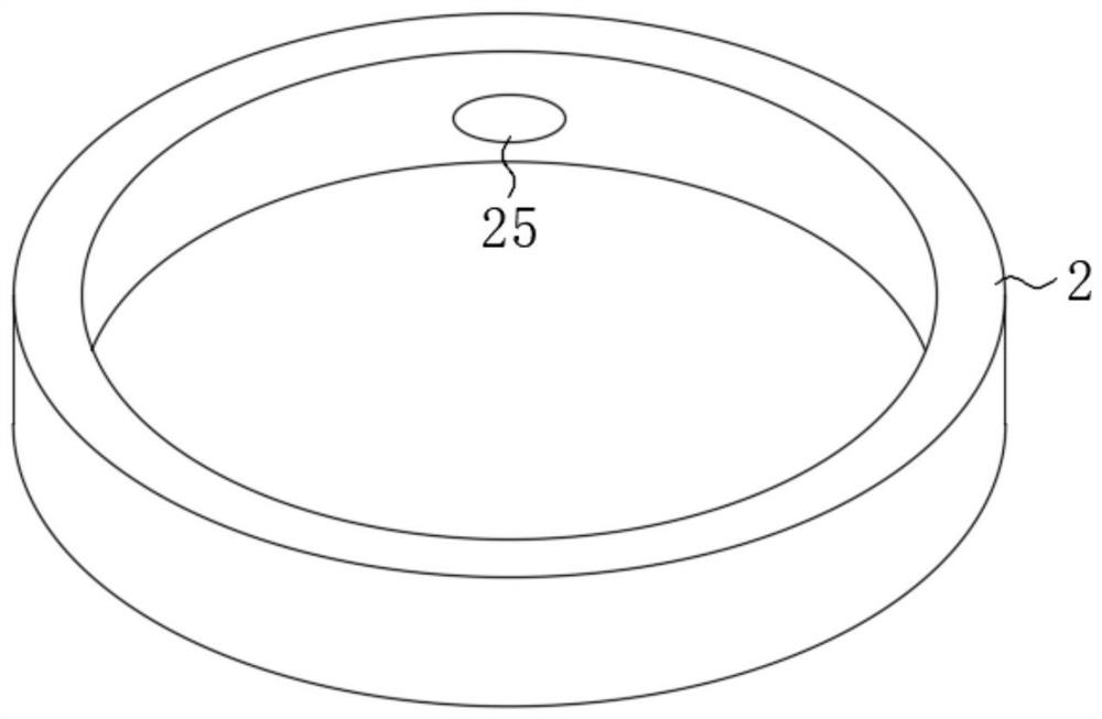
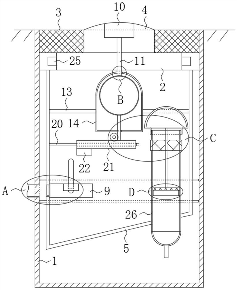
[0035] refer to Figure 1-7 , a new type of rainwater diversion well in sponge city, including a well cover and a water storage pipe 17 connected to the well body 1, the inner thread of the well body 1 is fixedly installed with an annular mounting seat 2, and the lower surface of the annular mounting seat 2 is fixedly installed with a guide tube 5;

[0036] The above points are worth noting:

[0037] 1. There are two groove bodies 25 on the inner wall of the annular mounting seat 2, and the setting of the groove bodies 25 is convenient to apply a force to the annular mounting seat 2 by hand to drive it to rotate.

[0038] 2. A layer of rubber ring can be partially fixed on the outer wall of the guide tube 5 (can not be set between the two 16), the elasticity of the rubber ring can make the guide tube 5 fit with the inner wall of the well body 1, and improve the guide tube 5 Stability in use.

[0039] 3. A detachable fixing method is used between the manhole cover and the an...

Embodiment 2

[0065] The difference between the second embodiment and the first embodiment is that the magnetic ring 24 is fixedly installed in the water outlet hole 15 , the side part of the floating block 9 close to the magnetic ring 24 is made of magnetic material, and the floating block 9 is close to the magnetic ring 24 side. A shielding rubber is fixedly installed on the outer wall of the .

[0066] The advantage of the second embodiment relative to the first embodiment is that the arrangement of the magnetic ring 24 and the shielding rubber enables the floating block 9 to shield the water storage pipe 17, and the shielding effect is better, avoiding heavy rain or continuous long-term light rain. Ditches or rain garden sponges input too much rain, causing plant leaves to turn yellow or directly washing away parts of the planting soil.


PUM


Abstract

The invention discloses a new type of rainwater diversion well in sponge city, comprising a well cover and a water storage pipeline connected with a well body. An annular mounting seat is threadedly fixed in the well body, and an inner wall of the annular mounting seat is provided with Two groove bodies, a guide tube is fixedly installed on the lower surface of the annular mounting seat; a floating block is installed in the guide tube through a sliding structure, and a water outlet matched with a water storage pipe is opened on the guide tube Two sealing rings matched with the water storage pipe are also fixedly installed on the guide cylinder, and the sealing rings are located on both sides of the water storage pipe. The advantage is that: the use of the water collecting seat, the magnetic block 1 and the magnetic block 2 can make the floating block move down and recover to the position when the water collecting seat is filled with rainwater in heavy rainy weather or continuous light rain weather for a long time. The water storage pipeline is shielded at the starting position to prevent excessive rainwater from being transported to the grass-planting ditch through the water storage pipeline and causing great damage.

Description

technical field [0001] The invention relates to the technical field of sponge cities, in particular to a new type of large and small rainwater diversion wells in sponge cities. Background technique [0002] Water wells are an important part of the sponge city structure. Today's water wells are equipped with a diversion function, which can store rainwater and directly irrigate the corresponding plants in light rainy weather, which has certain positive benefits, but it is transported in heavy rainy weather. The rain will cause excessive water in the planting part of the plant, which will have a certain impact on the normal production of the plant; [0003] After searching, the Chinese authorized utility model patent with the patent number CN207660076U discloses a new type of rainwater diversion well in sponge city, the well body is fixedly built in the lower part of the road surface, the well ring is placed on the upper end of the well body, and the rainwater grate is placed i...

Claims


Application Information

Patent Timeline
Patent Type & Authority Patents(China)
IPC IPC(8): E03F5/04E03F5/06E03F5/14E03F7/00
CPCE03F5/0404E03F5/06E03F5/14E03F7/00Y02A20/108
Inventor 陈清春
Owner ZHONGYIFENG CONSTR GRP
Why Eureka
Try Eureka