Knife components and food processors

A knife assembly and knife technology, applied in the field of food cooking machines, can solve the problem that the knife and the knife shaft are difficult to take into account the convenience of disassembly and assembly, safety and reliability, etc., and achieve the effect of simple and convenient disassembly operation

Active Publication Date: 2022-02-11
GUANGDONG MIDEA CONSUMER ELECTRICS MFG CO LTD
View PDF0 Cites 0 Cited by
  • Summary
  • Abstract
  • Description
  • Claims
  • Application Information

AI Technical Summary

Problems solved by technology

[0004] The first object of the present invention is to provide a knife assembly, which aims to solve the technical problem that the connection between the knife and the knife shaft in the existing food cooking is difficult to take into account the convenience of disassembly and assembly, safety and reliability

Method used


Image

  • Knife components and food processors
  • Knife components and food processors
  • Knife components and food processors

Examples


Embodiment 1

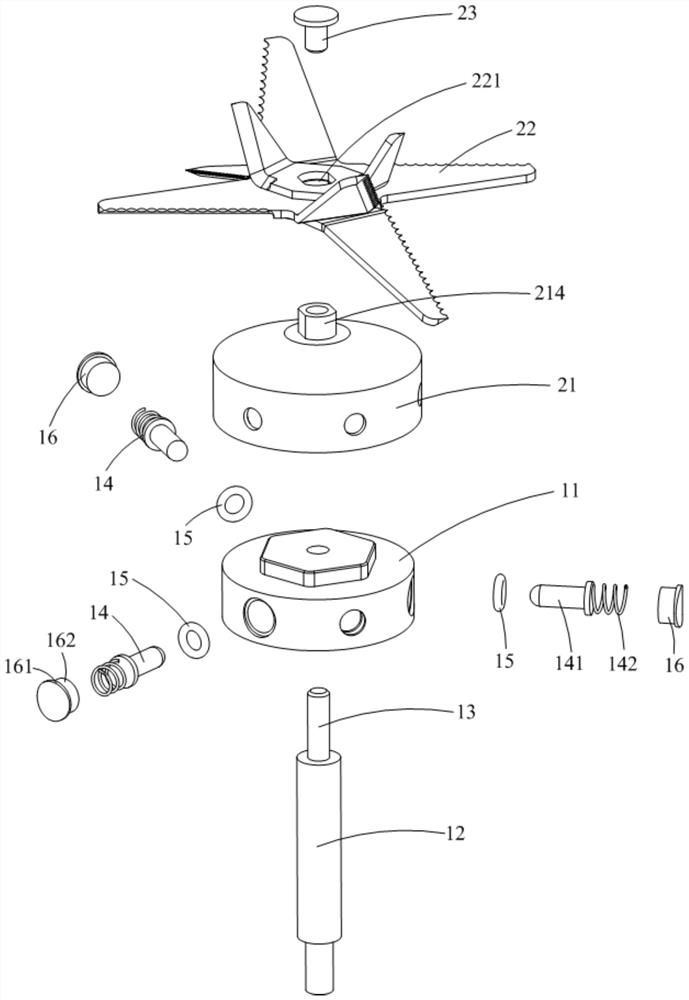
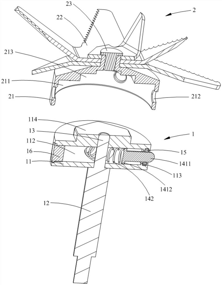
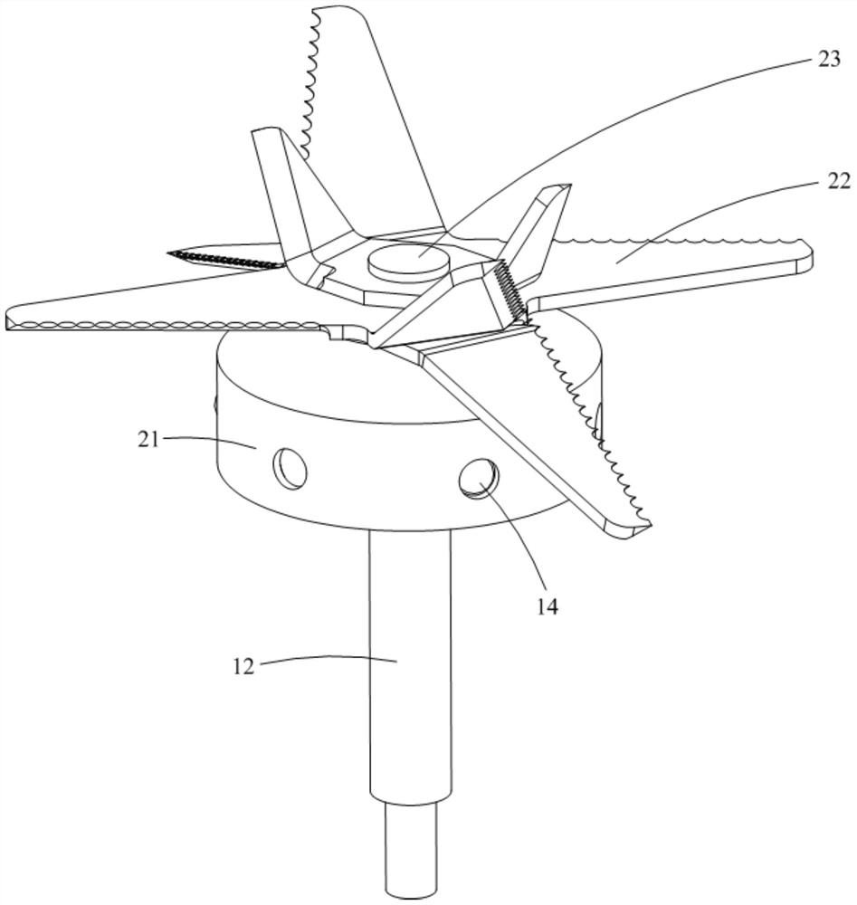
[0057] Such as Figure 1-9 As shown, the knife assembly 100 provided by Embodiment 1 of the present invention is used in a food cooking machine, and includes a knife shaft 1 and a knife 2 detachably mounted on the knife shaft 1. The bottom of the knife 2 is provided with a concave cavity 211, and the concave cavity 211 Positioning hole 212 is provided on the side wall; knife shaft 1 includes seat body 11, shaft body 12, support rod 13 and elastic member 14, seat body 11 is accommodated and positioned in concave cavity 211, shaft body 12 from seat body 11 The bottom extends downwards, the support rod 13 vertically passes through the connecting seat 201 body 11, and the elastic member 14 includes a positioning rod with one end arranged in the seat body 11 and the other end extending laterally out of the seat body 11 and inserted into the positioning hole 212 141 and two ends abut against the positioning rod 141 and the first elastic member 142 of the supporting rod 13 respective...

Embodiment 2

[0095] The main difference between the knife assembly 100 and the food cooking machine provided in this embodiment and the first embodiment is that the elastic member 14 is set differently, which is specifically reflected in: Figure 1-9 As shown, in Embodiment 1, the elastic member 14 only includes one elastic piece; Figure 10-12 As shown, in this embodiment, the elastic member 14 includes two elastic pieces. Specifically, in this embodiment, the elastic member 14 further includes a second elastic member 143 sheathed on the rod body 1411 , one end of the second elastic member 143 abuts against the convex cap 1412 , and the other end abuts against the shoulder 113 . In this embodiment, when the cutter assembly 100 is rotating, the positioning rod 141 can overcome the elastic force of the second elastic member 143 under the action of centrifugal force to compress the second elastic member 143 and protrude outward to increase the depth inserted into the positioning hole 212 a...

Embodiment 3

[0106] The main difference between the knife assembly 100 and the food cooking machine provided in this embodiment and the first and second embodiments is that the connection mode between the support rod 13 and the base body 11 is different, which is specifically reflected in: Figure 1-12 As shown, in Embodiment 1 and Embodiment 2, the support rod 13 realizes its locking connection with the seat body 11 through the cooperation of the external thread on it and the internal thread in the vertical mounting hole 111; Figure 13 As shown, in this embodiment, the nut 17 outside the vertical mounting hole 111 of the support rod 13 is locked and positioned on the base body 11 . Specifically, in this embodiment, the vertical mounting hole 111 is a light through hole, and the support rod 13 includes a main rod body 131 penetrating in the light through hole and a stud 132 passing through the light through hole from the top of the main rod body 131, The cutter shaft 1 also includes a nut...


PUM


Abstract

The invention is applicable to the field of household electrical appliances, and discloses a cutter assembly and a food cooking machine. The cutter assembly includes a cutter shaft and a cutter detachably mounted on the cutter shaft. There are positioning holes; the cutter shaft includes a base body, a shaft body, a support rod and an elastic member. The base body is accommodated and positioned in a concave cavity, the shaft body extends downward from the bottom of the base body, and the support rod is vertically connected to the base body The elastic member includes a positioning rod with one end arranged in the seat body, the other end protruding laterally out of the seat body and inserted into the positioning hole, and a first elastic member with two ends abutting against the positioning rod and the supporting rod respectively. The positioning rod is far away from the first elastic member. The end face of the piece is an inclined surface or an arc surface. In the present invention, when the cutter assembly rotates, the positioning rod will further protrude from the seat body and be inserted into the positioning hole under the action of centrifugal force, which prevents the vertical slippage of the cutter from the cutter shaft and ensures the stability of the cutter installed on the cutter shaft. Reliability, and the disassembly operation of the cutter and the cutter shaft is relatively convenient.

Description

technical field [0001] The invention relates to the field of household electrical appliances, in particular to a cutter assembly and a food cooking machine with the cutter assembly. Background technique [0002] A food cooking machine generally includes a base assembly, a cup assembly and a knife assembly. The cup assembly is placed on the base assembly. The knife assembly has a knife located in the cup assembly and a knife shaft that is connected to the base assembly and the knife by transmission. In the traditional technology, the cutter assembly is fixed on the chassis of the cup body assembly, and the cutter assembly cannot be disassembled or is not easily disassembled. In this way, during the specific use of the food processor, when the bottom of the food occurs, the cutter and the chassis It is very difficult to clean the food processing machine, which will cause dead ends in the food processing machine, which seriously affects the hygienic reliability of the product u...

Claims


Application Information

Patent Timeline
Patent Type & Authority Patents(China)
IPC IPC(8): A47J43/046A47J43/07
Inventor 招绍坤刘云祥唐燕
Owner GUANGDONG MIDEA CONSUMER ELECTRICS MFG CO LTD
Why Eureka
Try Eureka