
Material pressurizing device

A booster device and material technology, which is applied in the field of cement building materials, can solve the problems of high height, high floor height, concrete pillar height, size increase, etc., and achieve the effect of convenient maintenance and installation, simple structure and manufacture, and low installation difficulty

Pending Publication Date: 2019-05-03
NANJING XIPU CEMENT ENG GROUP
View PDF0 Cites 1 Cited by
  • Summary
  • Abstract
  • Description
  • Claims
  • Application Information

AI Technical Summary

Problems solved by technology

As a result, the floor height of the workshop where the roller press is located is relatively high, not only the height and size of the concrete pillars need to be increased, but also the height of the corresponding lifting equipment of the grinding system is also relatively high

Method used


Image

  • Material pressurizing device
  • Material pressurizing device
  • Material pressurizing device

Examples


Embodiment Construction

[0019] In order to make the objectives, technical solutions and advantages of the present invention clearer, the technical solutions in the embodiments of the invention will be clearly and completely described below in conjunction with the drawings in the embodiments of the invention. Obviously, the embodiments described below are only It is a part of the embodiments of the invention, but not all of them. Based on the embodiments of the invention, all other embodiments obtained by persons of ordinary skill in the art without making creative efforts belong to the protection scope of the invention.

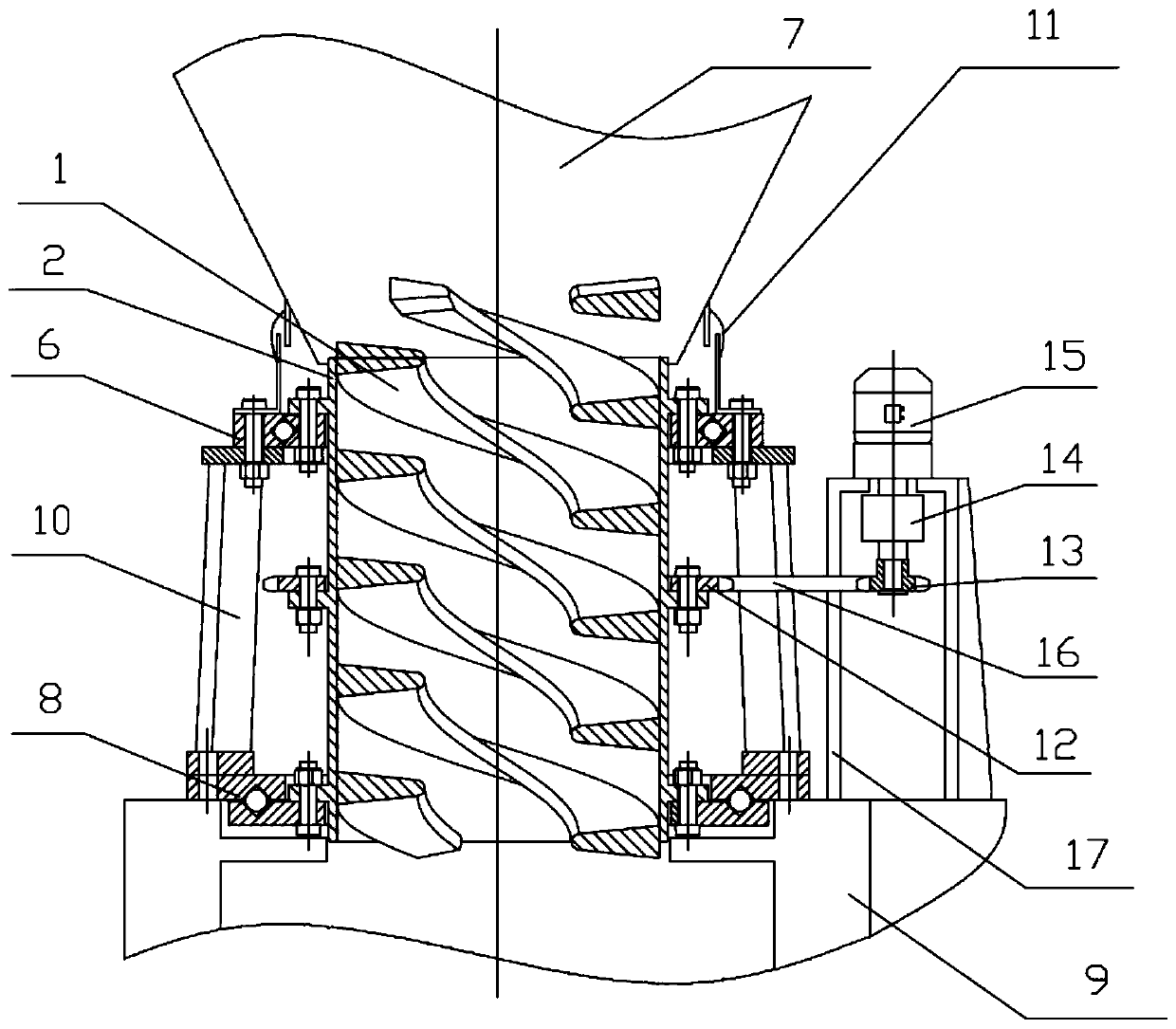
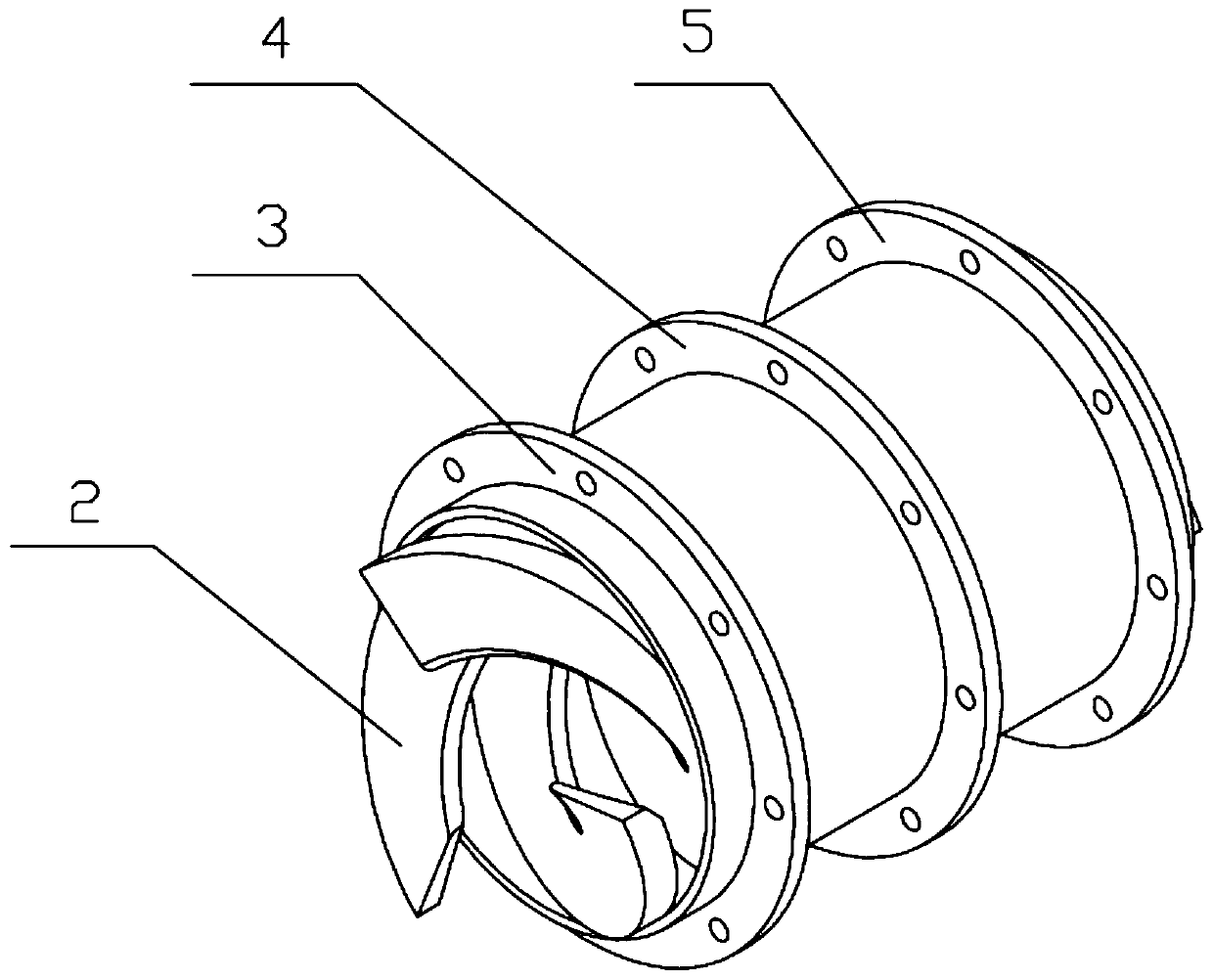
[0020] Such as Figures 1 to 2 As shown, a material pressurization device provided by the embodiment of the present invention includes a pipe body 1 made of wear-resistant material, the inside of the pipe body 1 is hollow, and the inner wall of the pipe body 1 is provided with a spiral body 2 that spins down. The outer wall of the pipe body 1 is provided with an upper flange 3 , a ...


PUM


Abstract

The invention provides a material pressurizing device, comprising a pipe body. The pipe body is hollow inside. The inner wall of the pipe body is provided with a downward spiral body. The outer wall of the pipe body is provided with an upper flange, a middle flange and a lower flange in sequence from top to bottom. A first rotation piece is fixed to the upper flange. An upper port of the pipe bodyis rotatably connected with a material bin through the first rotation piece. A driving device for driving the pipe body to rotate is fixed to the middle flange. A second rotation piece is fixed to the lower flange. A lower port of the pipe body is rotatably connected with a feeding inlet of a roller press through the second rotation piece. A first fixing support for fixing the first rotation piece and the second rotation piece is arranged between the first rotation piece and the second rotation piece. The first fixing support is fixed to a shell of the feeding inlet of the roller press. According to the material pressurizing device, the height between the material bin and the roller press can be greatly reduced so that the height of a workshop can be smaller, and cost in various aspects such as infrastructure, equipment height, equipment power and installation cost can be reduced.

Description

technical field [0001] The invention relates to the field of cement building materials, in particular to a material pressurization device. Background technique [0002] At present, in cement building materials and other industries, roller presses are widely used in raw material grinding, cement grinding and other links due to their efficient grinding and crushing efficiency. Because the principle of the roller press is that two rollers squeeze the material against each other, in order to ensure that the material enters the roll gap stably and smoothly during operation, and to maintain the continuous and stable operation of the roller press, the material entering the roller press must maintain a certain Material pressure. At present, the common solution in the process is to build the factory building of the roller press high, set up a stable material bin on the upper floor, and then connect it to the discharge port of the roller press through a 4 to 5 meter discharge pipe, a...

Claims


Application Information

Patent Timeline
IPC IPC(8): B02C4/28B02C23/02
CPCB02C23/02B02C4/28
Inventor 赵玉会曹国锋苑明华朱宽平孙云
Owner NANJING XIPU CEMENT ENG GROUP
Learn More