Data acquisition jig and method for closed impeller
A technology of data collection and closed impeller, which is applied in the field of centrifugal pumps, can solve the problems of insufficient fitting accuracy, data collection errors, and long fitting time, and achieve simple structure and production, accurate data collection, and simple and convenient production Effect
- Summary
- Abstract
- Description
- Claims
- Application Information
AI Technical Summary
Problems solved by technology
Method used
Image
Examples
Embodiment 1
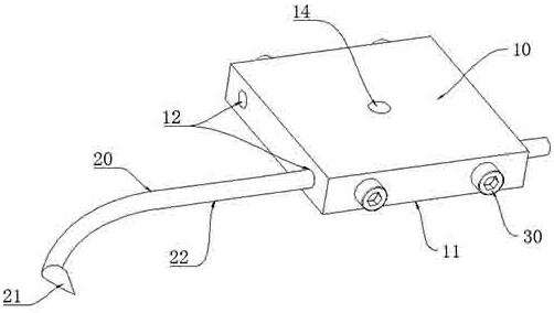
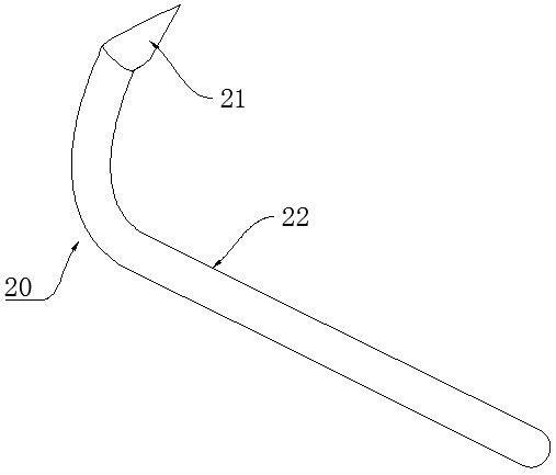
[0031]ReferFigure 1 to 3However, a non-limiting example of the present invention, the present invention provides a data acquisition fixture of a closed impeller, including jig 10 and probe 20, and the probe 20 consists of probe head 21 and the probe rod 22, said The probe rod 22 is made of a soft quality to be converted under external force. The shape of the probe rod 22 is in shape with the blade of the closed impeller, and the outer end of the probe rod 22 detachable fixed in the clamp 10. On the upper side of the probe rod 22, a probe head 21 is provided, and the tip of the probe head 21 is located on the plane of the clamp 10, or the needle tip of the probe head 21. The position is close to the plane 11 of the clamp 10. In this embodiment, the trigger is mainly composed of a clamp 10 of the probe 20 and the fixing probe 20, and its clamp 10 is prepared by a steel block, and the probe 20 is made of an elongated steel, and its overall component is small. Simple structure; specific...
Embodiment 2
[0040]ReferFigure 1 to 3Further, it is still another non-limiting example of the present invention, and a data acquisition method of closed impeller using data acquisition fixture using the above closed impeller, including the following steps.
[0041]S1, the preparation of the fixture, including the preparation of the probe 20 and jigs 10, the preparation of the probe 20, which is first made of copper strips or wire in which the wires that can be variable in the external force is deformorized into the impeller flow path. The shape of the blade is then prepared in the back of the curved probe 20; then selects a flat steel block to prepare the clamp 10, and the drill through hole 12 is performed on the steel block for mounting the probe 20. The adjustment hole 14 is provided in the adjustment hole 14 in the adjustment hole 14 in the steel block 12 and the penetrating hole 12 in which the self-through hole 12 is vertically discharged to the outer steel block, and the adjustment hole 14 i...
PUM
 Abstract
Description
Claims
Application Information
 - R&D
- Intellectual Property
- Life Sciences
- Materials
- Tech Scout
- Unparalleled Data Quality
- Higher Quality Content
- 60% Fewer Hallucinations
Browse by: Latest US Patents, China's latest patents, Technical Efficacy Thesaurus, Application Domain, Technology Topic, Popular Technical Reports.
© 2025 PatSnap. All rights reserved.Legal|Privacy policy|Modern Slavery Act Transparency Statement|Sitemap|About US| Contact US: help@patsnap.com


