Supercharge Your Innovation With Domain-Expert AI Agents!

Numerical control engraving machine capable of self-adaptive adjusting of workpieces

An adaptive adjustment, CNC engraving machine technology, applied in engraving, processing models, decorative arts, etc., can solve problems such as machine tool vibration, workpiece position offset, product processing problems, etc., to achieve the effect of simple control structure and improved precision

Pending Publication Date: 2019-05-03
ANHUI SUDA NUMERICAL CONTROL EQUIP
View PDF0 Cites 1 Cited by
  • Summary
  • Abstract
  • Description
  • Claims
  • Application Information

AI Technical Summary

Problems solved by technology

But this repetitive and unbiased pattern engraving feature exists in the pattern itself. Once the position of the workpiece changes on the machine tool for repetitive and unbiased pattern engraving, the relative position of the engraved pattern on the workpiece will also change, so that Will cause the workpiece to be scrapped
Usually, the feeding of CNC engraving machines is manual feeding. The disadvantage of manual feeding is that it is difficult to accurately position and correct the workpiece, especially for large or heavy workpieces.
Moreover, during the processing, as the tool feeds and moves, the machine tool will generate certain vibrations that will cause the workpiece to shift in position, which will also cause problems in product processing

Method used


Image

  • Numerical control engraving machine capable of self-adaptive adjusting of workpieces
  • Numerical control engraving machine capable of self-adaptive adjusting of workpieces
  • Numerical control engraving machine capable of self-adaptive adjusting of workpieces

Examples


Embodiment

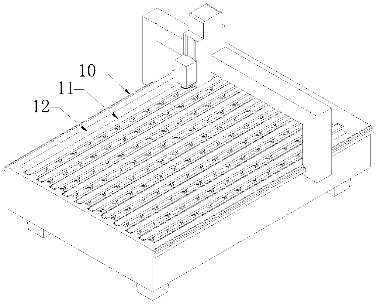
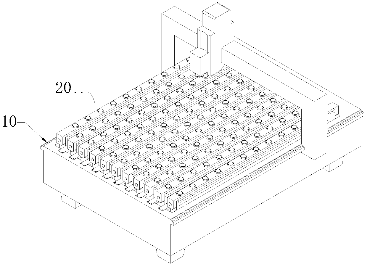
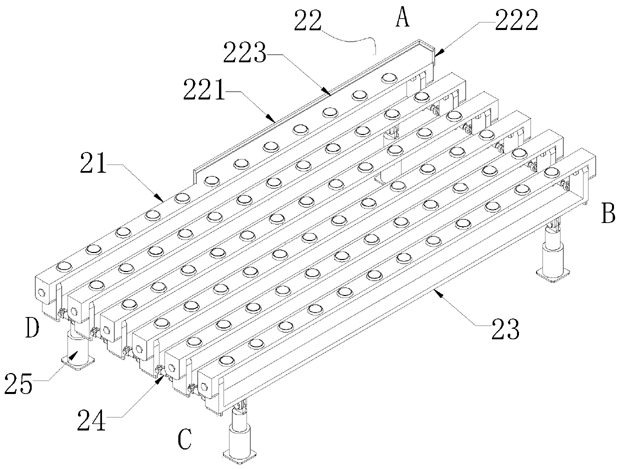
[0021] Such as Figures 1 to 3 As shown, the CNC engraving machine for workpiece self-adaptive adjustment includes a frame 10, a grid plate 11 fixedly installed on the top surface of the frame 10, a chip collection groove 12 is provided below the grid plate 11, and the chip collection groove 12 A telescopic workpiece calibration device 20 is fixedly installed, and the workpiece calibration device 20 includes a top plate 21 for lifting the workpiece, a positioning angle 22 arranged on the top surface of the top plate 21, a support plate 23 connected in rotation with the top plate, and connected adjacent The telescoping device 24 of the support plate 23 and the cylinder 25 that controls the vertical movement of the support plate 23, the positioning angle 22 is set at a corner of the workpiece alignment device 20, the support plate 23 and the grid plate 11 are arranged at intervals, and the cylinder The cylinder base bottom of 25 is fixedly connected with the groove bottom of chi...


PUM


Abstract

The invention discloses a numerical control engraving machine capable of self-adaptive adjusting of workpieces. The numerical control engraving machine comprises a machine frame and grid plates fixedly installed on the top surface of the machine frame, wherein chip collecting grooves are formed below the grid plates; telescopic workpiece alignment devices are fixedly installed in the chip collecting grooves, and the workpiece alignment devices comprise top plates with the effect of lifting, positioning corners arranged on the top surfaces of the top plates, supporting plates rotatably connected with the top plate, telescopic device connecting the adjacent supporting plates and air cylinders controlling the supporting plates to move vertically, wherein the positioning corners are arranged at one corners of the workpiece alignment devices; the supporting plates and the grid plates are arranged at cross intervals; and the bottoms of cylinder seats of the air cylinders are fixedly connected with the groove bottoms of the chip collecting grooves, and telescopic rods of the air cylinders are rotatably connected with the bottoms of the supporting plates. According to the numerical controlengraving machine, the workpiece alignment devices are arranged in the chip collecting grooves, the space of the numerical control engraving machine is utilized to the maximum extent, the self-adaptive adjustment of the workpieces is realized by gravity, the control structure is simple, and the accuracy, efficiency and convenience of workpiece alignment are greatly improved.

Description

technical field [0001] The invention belongs to the technical field of engraving and milling machines, in particular to a numerically controlled engraving machine with adaptive adjustment of workpieces. Background technique [0002] CNC engraving machine is an automatic control processing machine, which can carry out repetitive and unbiased pattern engraving according to the pre-set engraving program. But this repetitive and unbiased pattern engraving feature exists in the pattern itself. Once the position of the workpiece changes on the machine tool for repetitive and unbiased pattern engraving, the relative position of the engraved pattern on the workpiece will also change, so that It will cause the workpiece to be scrapped. Usually, the feeding of CNC engraving machines is manual feeding. The disadvantage of manual feeding is that it is difficult to accurately position and correct the workpiece, especially the workpiece with large volume or mass. Moreover, during the ma...

Claims


Application Information

Patent Timeline
IPC IPC(8): B44B1/00B44B1/06B44B3/00B44B3/06
CPCY02P70/10
Inventor 罗群罗亮
Owner ANHUI SUDA NUMERICAL CONTROL EQUIP
Features
  • R&D
  • Intellectual Property
  • Life Sciences
  • Materials
  • Tech Scout
  • Unparalleled Data Quality
  • Higher Quality Content
  • 60% Fewer Hallucinations
Learn More