

Retaining wall soil pressure model test device under plane strain condition and test method thereof
A technology of plane strain and model experiment, which is applied to the test of basic structures, underwater structures, buildings, etc., can solve the problems of inconsistency between test conditions and plane strain assumptions, and achieve the elimination of boundary effects, easy processing, and convenient processing Effect
Pending Publication Date: 2019-05-03
SHANDONG UNIV
View PDF0 Cites 2 Cited by
- Summary
- Abstract
- Description
- Claims
- Application Information
AI Technical Summary
Problems solved by technology
Therefore, the inventors found that it is necessary to carry out research on the earth pressure distribution of the retaining wall under different displacement modes, and the research on the relationship between the earth pressure a
Method used
View moreImage
Smart ImageViewing Examples

Examples
 PUM
 Abstract
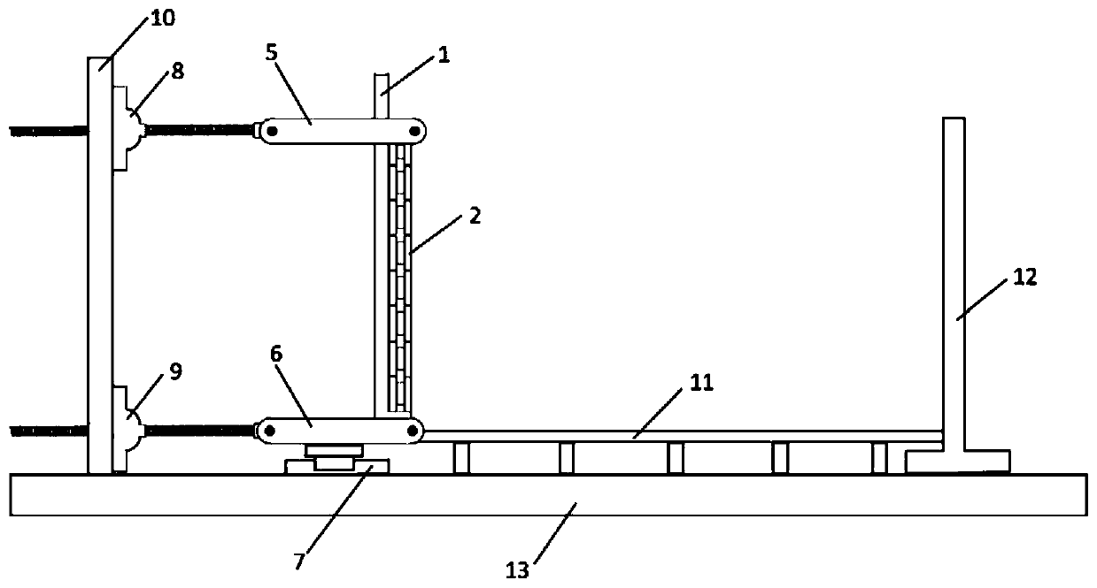
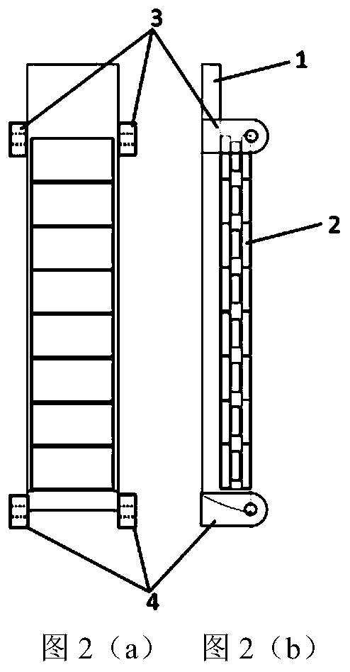
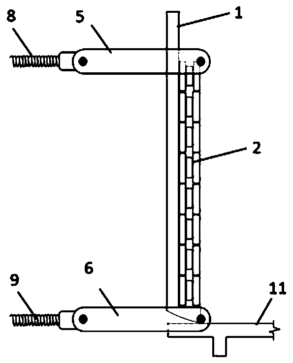
The invention discloses a retaining wall soil pressure model test device under the plane strain condition and a test method thereof. The problem that the simulation of a test device in the prior art is inconsistent with actual engineering is solved. The retaining wall soil pressure model test device and the test method thereof have the beneficial effects of realizing the determination of the relation between soil pressure and lateral displacement under different displacement modes, realizing the assumption of plane strain in a complete sense, greatly reducing the model size and simplifying thetest steps. According to the scheme, the retaining wall soil pressure model test device comprises a U-shaped structure, a main wall body on one side, a side wall and a plurality of propulsion mechanisms, wherein a plurality of pressure sensors are arranged on the surface of the main wall body, the side wall surrounds the U-shaped structure, and the U-shaped structure is internally provided with fillers; and the propulsion mechanisms are correspondingly connected with the main wall body, and the propulsion mechanisms are arranged up and down to enable the upper half section and/or the lower half section of the main wall body to rotate or translate relative to a soil retaining base under the drive of the two groups of propulsion mechanisms.
Description
technical field [0001] The invention relates to the field of road engineering, in particular to a retaining wall earth pressure model experiment device and a test method under plane strain conditions. Background technique [0002] With the increasing shortage of cultivated land resources in our country and the increasing shortage of land resources in expressway construction, the technology of retaining walls instead of high embankment slopes has attracted extensive attention from the engineering community. In the design of retaining walls, the problem of earth pressure behind the wall has been widely concerned by the academic and engineering circles, because the determination of earth pressure is directly related to the structural calculation and overall stability calculation of the retaining wall. The traditional limit equilibrium method of retaining wall design is based on the assumption of plane strain, assuming that the retaining wall rotates around the bottom, producing...
Claims
Login to View More Application Information
Patent Timeline
 IPC IPC(8): E02D33/00E02D29/02
Inventor宋修广张宏博鲁亮岳红亚
OwnerSHANDONG UNIV