Overlap joint type active cooling structure

An active cooling, oblique hole technology, applied in the direction of machine/engine, exhaust port of power unit, jet propulsion unit, etc., to achieve the effect of achieving structure, high overflow heat exchange efficiency, and avoiding uneven temperature distribution

Inactive Publication Date: 2019-05-03
XIAN AIRCRAFT DESIGN INST OF AVIATION IND OF CHINA
View PDF4 Cites 3 Cited by
  • Summary
  • Abstract
  • Description
  • Claims
  • Application Information

AI Technical Summary

Problems solved by technology

[0007] The purpose of the present invention is to design an overlapping active cooling structure to achieve thermal protection indicators and infrared stealth targets while solving the technical problems of weight reduction optimization and elimination of thermal mismatch and high temperature thermal stress inside the structure

Method used


Image

  • Overlap joint type active cooling structure
  • Overlap joint type active cooling structure
  • Overlap joint type active cooling structure

Examples


Embodiment Construction

[0027] Below in conjunction with accompanying drawing, the present invention is described in detail as follows:

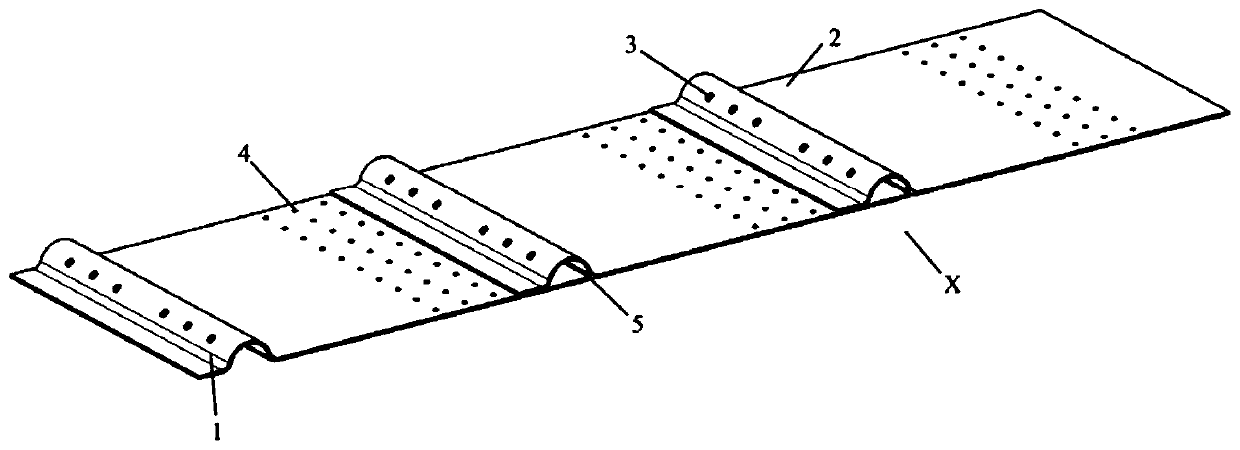
[0028] 1. The overall structure:

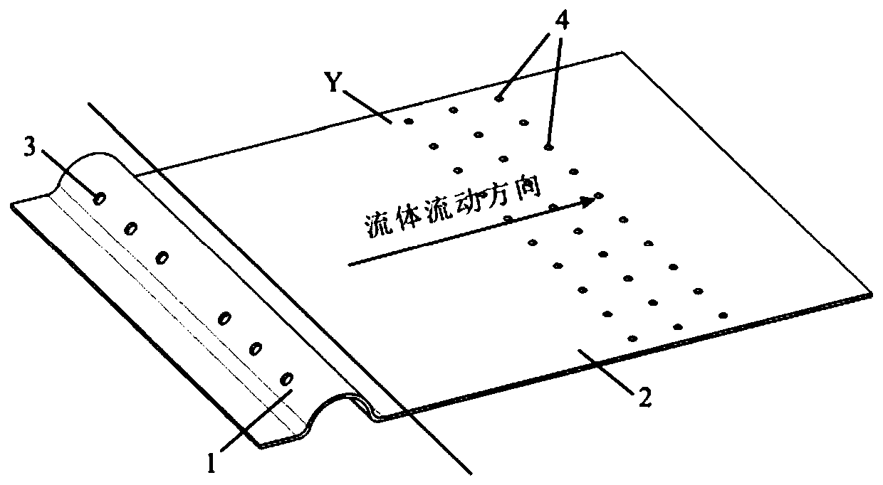
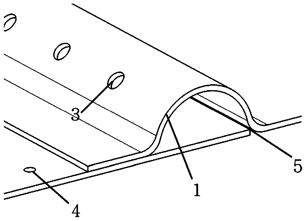
[0029] The overlapping active cooling structure of the present invention adopts the concept of segmented design, and the schematic diagram of the overall structure is as follows figure 1 As shown, it consists of overlapping active cooling units, where the schematic diagram of the active cooling unit is shown in figure 2 As shown, the active cooling unit is a corrugated structure, including an upper lap area 1 and a flat plate area 2; the upper lap area 1 is in the shape of a "wave crest" with a straight end, and there is an impact gas film hole on it 3. The flat plate area 2 is flat, with a slanted hole 4 in the lower end area, and the angle α between the axis of the slanted hole 4 and the airflow direction is an acute angle, and its enlarged view is as follows Figure 4 Shown; the end of the plate area 2 is lapped and fixed wi...


PUM


Abstract

The invention belongs to the technical field of thermal protection and particularly relates to an overlap joint type active cooling structure. The segmented design thought is adopted for the active cooling structure. The active cooling structure is capable of active cooling units in a tile type overlap joint mode. Each active cooling unit is of a similar corrugated structure and comprises an upperoverlap joint area (1) and a flat board area (2), wherein the upper overlap joint area (1) is shaped like a wave crest with a flat and straight tail end and is provided with impact air film holes (3); and the flat board area (2) is provided with inclined holes (4). By adopting the overlap joint type active cooling structure, the purposes of weight reduction optimization, thermal protection and infrared stealth of the structure are achieved, and the problem of increasing of thermal stress of the structure due to uneven temperature distribution is avoided.

Description

technical field [0001] The invention belongs to the technical field of heat protection, and in particular relates to an overlapping active cooling structure. Background technique [0002] At present, in the design of infrared stealth and heat protection of aircraft exhaust pipes, it is very common to use double-layer ejection cooling exhaust pipes. The inner layer of the exhaust pipe is usually designed as a whole. Due to the large temperature gradient between the inner and outer layers, it will cause many problems when both the inner and outer layers are under load. There are mainly the following problems: [0003] (1) The high-temperature core flow has radial pressure on the exhaust pipe, and the special-shaped exhaust pipe cannot achieve self-balance due to its shape; [0004] (2) The double-layer injection cooling structure is applied to the design of the exhaust pipe. When the inner and outer layers are firmly connected and both bear force, due to the large temperatur...

Claims


Application Information

Patent Timeline
Patent Type & Authority Applications(China)
IPC IPC(8): F02K1/82B64D33/04
Inventor 张瑞平李东李超
Owner XIAN AIRCRAFT DESIGN INST OF AVIATION IND OF CHINA
Why Eureka
Try Eureka