Lap joint type ejector cooling structure

A cooling structure and tile-type technology, applied in the direction of machines/engines, jet propulsion devices, etc., to achieve the effect of protecting against damage and avoiding high temperature thermal stress

Inactive Publication Date: 2019-05-03
XIAN AIRCRAFT DESIGN INST OF AVIATION IND OF CHINA
View PDF4 Cites 1 Cited by
  • Summary
  • Abstract
  • Description
  • Claims
  • Application Information

AI Technical Summary

Problems solved by technology

[0006] The purpose of the present invention is to design a lap joint ejection cooling structure to achieve thermal protection indicators and infrared stealth targets while solving the technical problems of weight reduction optimization and elimination of thermal mismatch and high temperature thermal stress inside the structure

Method used


Image

  • Lap joint type ejector cooling structure
  • Lap joint type ejector cooling structure
  • Lap joint type ejector cooling structure

Examples


Embodiment Construction

[0024] Below in conjunction with accompanying drawing, the present invention is described in detail as follows:

[0025] 1. The overall structure:

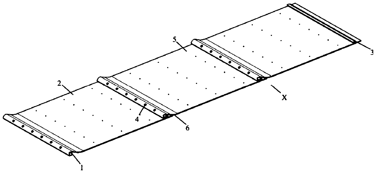
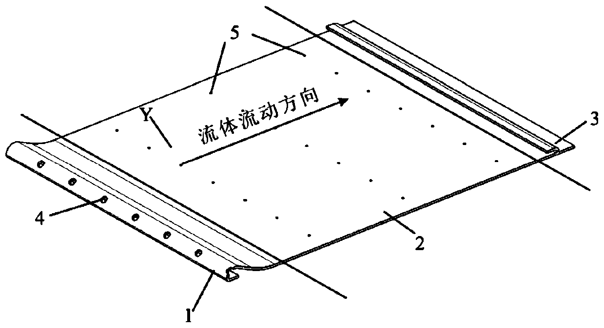
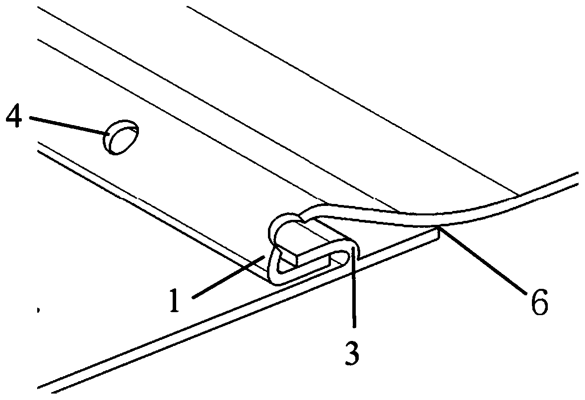
[0026] The schematic diagram of the overall structure of the lap joint ejection cooling structure of the present invention is as follows: figure 1 As shown, the cooling structure adopts the idea of ​​segmented design, and is composed of cooling structural units through tile lap joints, such as figure 2 shown. The cooling structural unit is an improvement on the longitudinal corrugated heat shield, including an upper overlapping area 1, a flat plate area 2, and a lower overlapping area 3; the upper overlapping area 1 is corrugated-like, and the transverse The cross section is in the shape of a hook, and the end of the hook is straight, and there is an impact air film hole 4 on it; the lower lap area 3 is in the shape of a buckle, and the cross section along the airflow direction is in the shape of a hook, and the end of the curv...


PUM

PropertyMeasurementUnit
Diameteraaaaaaaaaa
Diameteraaaaaaaaaa

Abstract

The invention belongs to the technical field of thermal protection, and particularly relates to a lap joint type ejector cooling structure. By adopting the thought of segmentation design, the structure is composed of a cooling structure unit through tile lap joint, wherein the cooling structure unit is of ripple-like structure and comprises an upper lapping area (1), a flat plate area (2), and a lower lapping area (3); the upper lapping area (1) is shaped as ripples and provided with impact film holes (4); the lower lapping area (3) is shaped as a lock catch; and inclined holes are formed in the flat plate area (2). Loss of weight and optimization of the structure, thermal protection, and infrared stealth are achieved by means of the lap joint type ejector cooling structure, and the problem of self thermal-stress increase caused by unevenly distributed temperatures is avoided.

Description

technical field [0001] The invention belongs to the technical field of heat protection, and in particular relates to a lap joint ejection cooling structure. Background technique [0002] At present, in the heat protection and infrared stealth design of aircraft exhaust pipes, most of the exhaust pipes are designed as double-layer injection cooling structures. Moreover, the inner and outer layers of the exhaust pipe are basically made of the same material as a whole. In the case of both inner and outer double layers bearing force, many problems may be caused due to the large temperature gradient. There are mainly the following problems: [0003] (1) The double-layer injection cooling structure is applied to the exhaust pipe. In the case of solid connection between the inner and outer layers, the higher temperature difference between the inner and outer layers will cause greater high-temperature thermal stress, which may cause lead to structural failure; [0004] (2) The l...

Claims


Application Information

Patent Timeline
IPC IPC(8): F02K1/82
Inventor 张瑞平赵楠赵建华
Owner XIAN AIRCRAFT DESIGN INST OF AVIATION IND OF CHINA
Why Eureka
Try Eureka