
Magnetic bearing vibration isolation and impact resistance control method and system

A control method and magnetic bearing technology, applied in the directions of bearings, shafts and bearings, mechanical equipment, etc., can solve the problems of small equivalent stiffness, large displacement of supported objects, loss of static bearing capacity, etc.

Active Publication Date: 2019-05-03
TSINGHUA UNIV
View PDF7 Cites 6 Cited by
  • Summary
  • Abstract
  • Description
  • Claims
  • Application Information

AI Technical Summary

Problems solved by technology

The traditional rotating machinery support system is generally a passive support system, which is difficult to be designed to have characteristics that are beneficial to the vibration isolation and impact resistance of the rotating machinery, and once the structure is determined, its dynamic characteristics will also be determined, and it is difficult to change again
[0003] In addition, according to the classical vibration theory, for the linear magnetic bearing system, there is always a compromise between the vibration isolation performance and the load-carrying performance of the system, that is, according to the vibration isolation principle, in order to ensure better vibration isolation effect and wide frequency band including low frequency For vibration isolation, the smaller the equivalent stiffness of the support system, the better, but the smaller the stiffness of the support system, the greater the displacement of the supported object under static force, that is, the loss of static bearing capacity

Method used


Image

  • Magnetic bearing vibration isolation and impact resistance control method and system
  • Magnetic bearing vibration isolation and impact resistance control method and system
  • Magnetic bearing vibration isolation and impact resistance control method and system

Examples


Embodiment Construction

[0069] The present invention will be further described in detail below in conjunction with the accompanying drawings and specific embodiments.

[0070] Traditional rotating machinery support systems are generally passive support systems, which are difficult to design to have favorable characteristics for vibration isolation and impact resistance of rotating machinery, and once the structure is determined, its dynamic characteristics will also be determined, and it is difficult to change again.

[0071] In order to solve these problems, the present invention proposes a nonlinear control method for magnetic bearing vibration isolation and shock resistance, which utilizes the active controllability of the magnetic bearing system and uses a control algorithm to realize that the magnetic bearing has high static and low dynamic nonlinear dynamic characteristics. Not only can it ensure excellent vibration isolation and impact resistance performance while taking into account the bearin...


PUM


Abstract

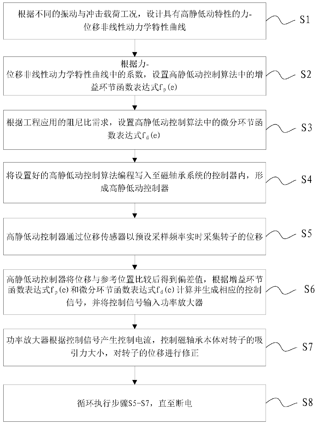
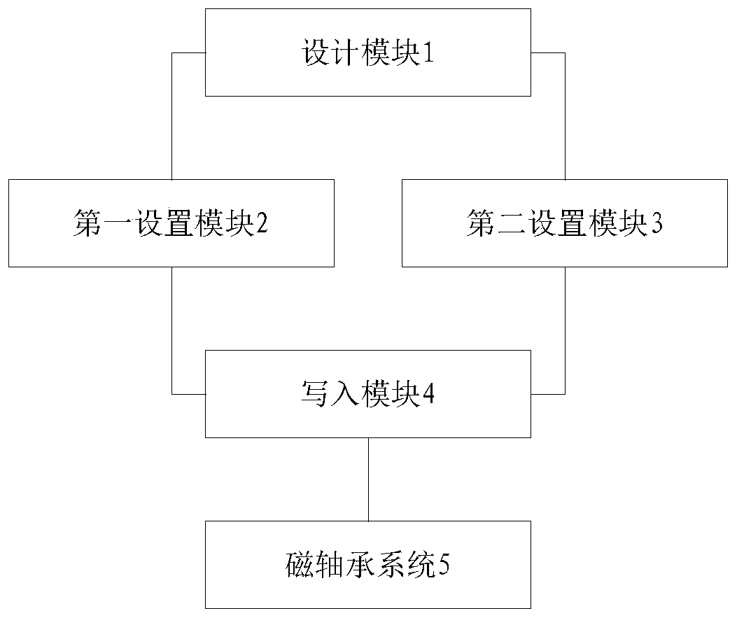
The invention discloses a magnetic bearing vibration isolation and impact resistance control method and system. The magnetic bearing vibration isolation and impact resistance control method and systemare applied to a magnetic bearing system. The method comprises the following steps of S1, designing a force-displacement nonlinear dynamic characteristic curve with high static and low dynamic characteristics according to different vibration and impact load working conditions; S2, setting a gain link function expression fp (e) in a high static and low dynamic control algorithm according to coefficients in the force-displacement nonlinear dynamic characteristic curve; S3, setting a differential link function expression fd (e) in the high static and low dynamic control algorithm according to damping ratio requirements of engineering applications; and S4, programming the set high static and low dynamic control algorithm into a controller of the magnetic bearing system to form a high static and low dynamic controller. According to the method and system, the active controllability of the magnetic bearing is utilized, and the control algorithm is used for realizing the condition that the magnetic bearing has high static and low dynamic nonlinear dynamic characteristics, namely, high static bearing capacity and low dynamic rigidity.

Description

technical field [0001] The invention relates to the technical field of magnetic bearing vibration isolation and shock resistance, in particular to a magnetic bearing vibration isolation and shock resistance control method and system. Background technique [0002] Improving the vibration isolation and shock resistance of rotating machinery is of great significance and value in industrial applications. Traditional rotating machinery support systems are generally passive support systems, which are difficult to design to have favorable characteristics for vibration isolation and impact resistance of rotating machinery, and once the structure is determined, its dynamic characteristics will also be determined, and it is difficult to change again. [0003] In addition, according to the classical vibration theory, for the linear magnetic bearing system, there is always a compromise between the vibration isolation performance and the load-carrying performance of the system, that is, ...

Claims


Application Information

Patent Timeline
IPC IPC(8): F16C32/04
Inventor 苏一新姚依晨马彦会于溯源
Owner TSINGHUA UNIV
Learn More