
Near-space real-time in-site wind speed and direction sensor based on wind pressure prediction

A technology of near space and wind speed and direction, which is applied to the measurement of fluid velocity, instruments, measuring devices, etc. using differential pressure, which can solve the problems of inability to obtain specific values ​​of wind speed and direction, weak wind pressure, and large influence of temperature changes.

Inactive Publication Date: 2019-05-03
INST OF ELECTRONICS CHINESE ACAD OF SCI
View PDF11 Cites 2 Cited by
  • Summary
  • Abstract
  • Description
  • Claims
  • Application Information

AI Technical Summary

Problems solved by technology

[0005] In view of this, the present disclosure provides a real-time in-situ wind speed and direction sensor in adjacent space based on wind pressure prediction, which is based on the principle of pressure difference, so as to alleviate the large influence of temperature change in the measurement of wind speed and direction in adjacent space in the prior art, and the air density changes with the air density. The wind pressure changes with the change of height and is small, so the wind pressure is very weak, and the conventional wind pressure test method cannot obtain the specific value of wind speed and direction and other technical problems

Method used


Image

  • Near-space real-time in-site wind speed and direction sensor based on wind pressure prediction
  • Near-space real-time in-site wind speed and direction sensor based on wind pressure prediction
  • Near-space real-time in-site wind speed and direction sensor based on wind pressure prediction

Examples


Embodiment Construction

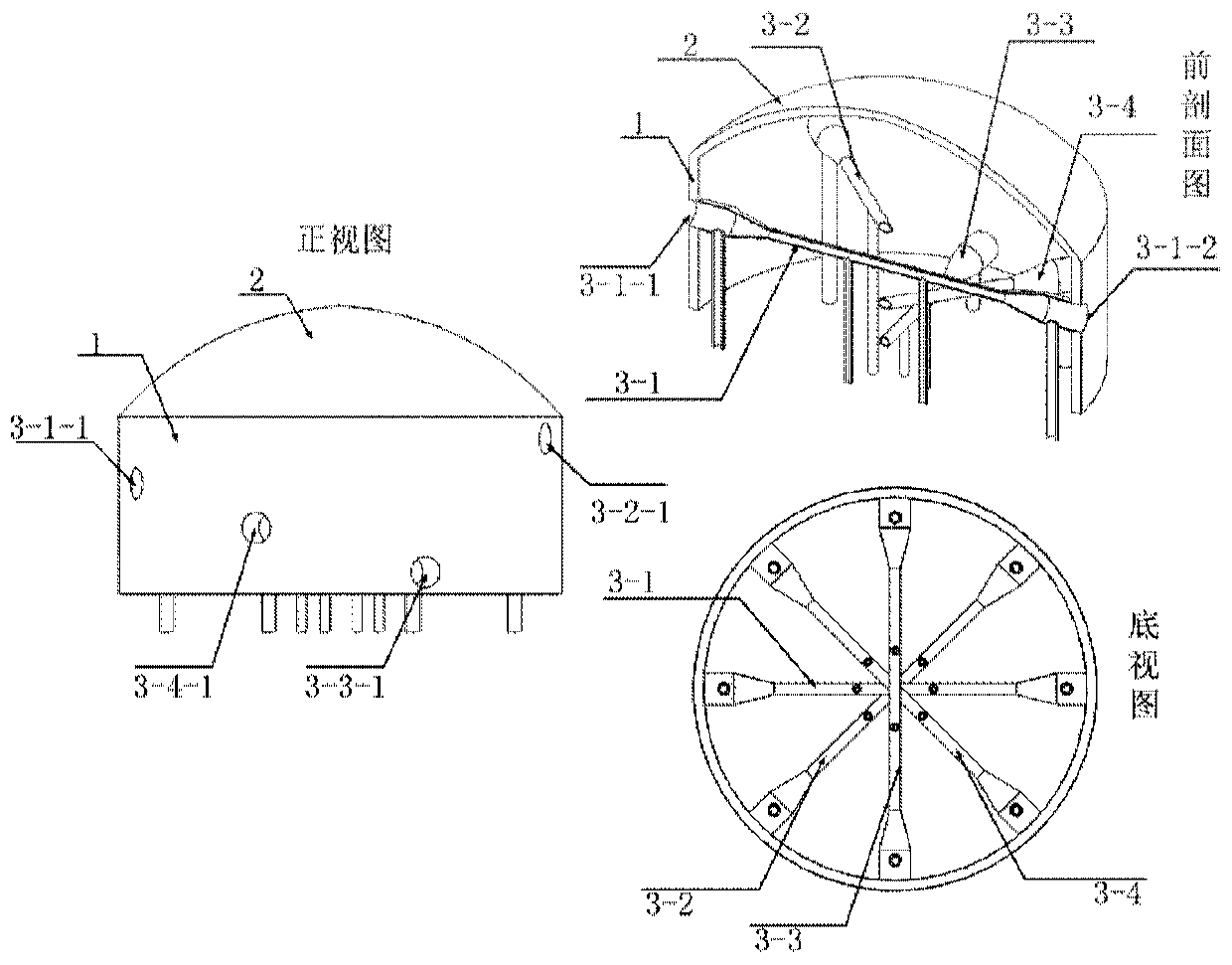
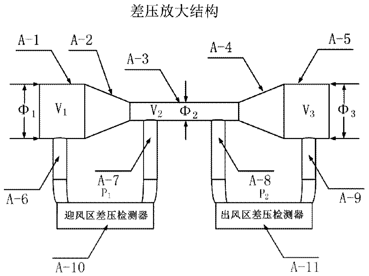
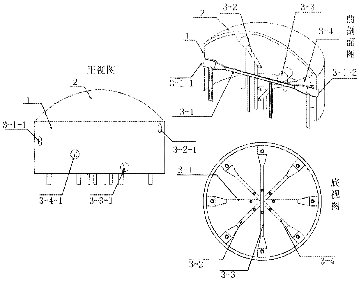
[0034] In view of this, the purpose of this disclosure is to provide a real-time in-situ wind speed and direction sensor in adjacent space based on wind pressure prediction. The sensor uses the principle of differential pressure to measure wind speed and direction through a solid-state two-dimensional wind speed and direction measurement method; for To solve the influence of high-altitude air density on wind pressure, the unique differential pressure amplification structure can be used to realize the measurement of wind differential pressure in adjacent spaces; the differential pressure amplification structure is realized by hollow tubes of different diameters, which is less affected by temperature.

[0035] In order to make the purpose, technical solutions and advantages of the present disclosure clearer, the present disclosure will be further described in detail below in conjunction with specific embodiments and with reference to the accompanying drawings.

[0036] The presen...


PUM


Abstract

The disclosure provides a near-space real-time in-site wind speed and direction sensor based on wind pressure prediction. The sensor comprises a housing in a cylindrical shape, a top cover arranged above the housing, n differential pressure amplifying structures, windward-zone differential pressure detection devices, and air-out differential pressure detection devices. The n differential pressureamplifying structures are used for amplifying the differential pressure of wind fluid, wherein the n is larger than or equal to 3; the differential pressure amplifying structures have hollow tube shapes with the thin middle parts and two thick ends and are arranged along different cross sections of the housing; circular holes are formed at connection parts between the two ends of the differentialpressure amplifying structures and the cylindrical wall of the housing; and the differential pressure amplifying structures includes windward zones, middle sections, and air-out zones. The windward-zone differential pressure detection devices are arranged at the windward zones by differential pressure detecting tubes and are used for measuring the differential pressures in the windward zones. Theair-out differential pressure detection devices arranged in the air-out zones by the differential pressure detecting tubes are used for measuring the differential pressures in the air-out zones. And then the wind speed and wind direction of near space are calculated based on the pressure differences in the windward zones and the air-out zones. Therefore, a technical problem that the wind speed anddirection measurement of the near space is affected by the temperature and height greatly in the prior art can be solved.

Description

technical field [0001] The disclosure belongs to the field of sensor design and preparation, and particularly relates to a real-time in-situ wind speed and direction sensor in an adjacent space based on wind pressure prediction. Background technique [0002] Due to the difference between the low temperature and low pressure environment in the adjacent space and the ground environment, conventional ground wind measuring devices cannot be used for the measurement of high-altitude atmospheric wind field. Balloonsondes, dropsondes, and rocketsondes and other wind measurement methods use sounding balloons or parachutes as wind tracers to measure wind fields, and can only detect a certain amount of wind field in the adjacent space at one time. One point, it cannot meet the real-time and in-situ spatial wind field detection requirements. The China Aerospace Aerodynamics Technology Research Institute published a paper "Development of Low-Speed ​​Aircraft Anemometer in Near Space an...

Claims


Application Information

Patent Timeline
IPC IPC(8): G01P5/14G01P13/02
Inventor 杜利东赵湛方震
Owner INST OF ELECTRONICS CHINESE ACAD OF SCI
Learn More