
Testing circuit for cascaded converter multi-submodule multi-working condition simulation

A technology for testing circuits and converters, applied in the direction of measuring electricity, parts and instruments of electrical measuring instruments, etc., can solve the problem that the converter system and operating parameters cannot be adjusted flexibly, no instructions or reports are found, expensive time, economical Cost and other issues, to achieve the effect of improving test efficiency, reducing test cost, and improving flexibility

Active Publication Date: 2019-05-03
SHANGHAI JIAO TONG UNIV
View PDF12 Cites 9 Cited by
  • Summary
  • Abstract
  • Description
  • Claims
  • Application Information

AI Technical Summary

Problems solved by technology

However, the traditional cascaded converter sub-module test method needs to build a relatively complete cascaded converter system, and its limitations are:
[0003] 1) Building the system brings high time and economic costs;
[0004] 2) Great power loss during the test;
[0005] 3) The system and operating parameters of the converter cannot be adjusted flexibly
[0007] At present, there is no description or report of the similar technology of the present invention, and no similar data at home and abroad have been collected yet.

Method used


Image

  • Testing circuit for cascaded converter multi-submodule multi-working condition simulation
  • Testing circuit for cascaded converter multi-submodule multi-working condition simulation
  • Testing circuit for cascaded converter multi-submodule multi-working condition simulation

Examples


Embodiment Construction

[0036] The present invention will be described in detail below in conjunction with specific embodiments. The following examples will help those skilled in the art to further understand the present invention, but do not limit the present invention in any form. It should be noted that those skilled in the art can make several changes and improvements without departing from the concept of the present invention. These all belong to the protection scope of the present invention.

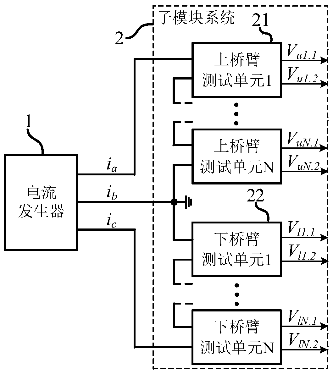
[0037] The embodiment of the present invention provides a test circuit for multi-submodule multi-working condition simulation of cascaded converters. The cascaded converters that can be simulated include but are not limited to half-bridge and full-bridge modular multi-level converters. Modular Multilevel Converter (MMC) and Cascaded H-Bridge Converter (CHB). The test circuit of the embodiment of the present invention includes:

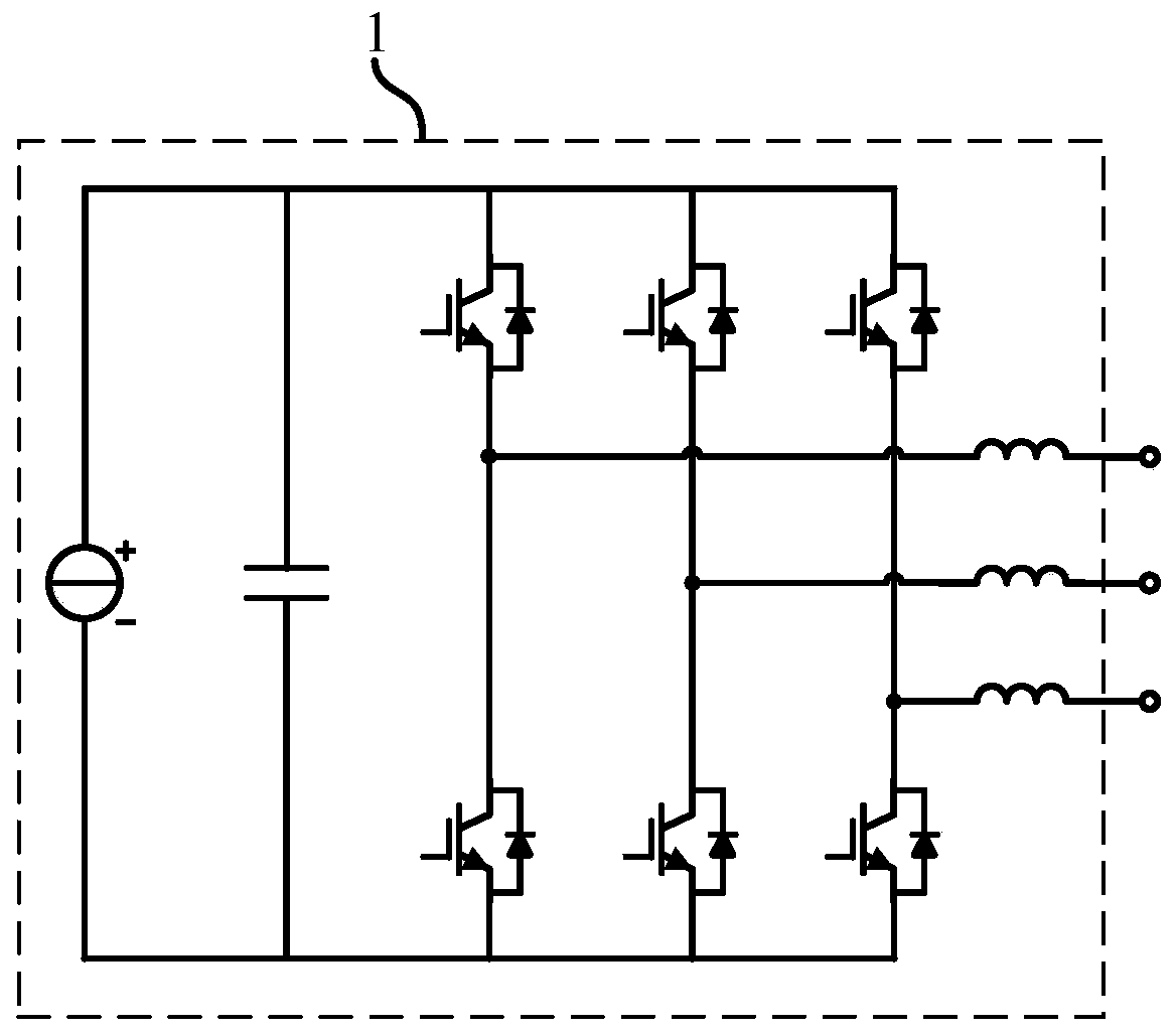
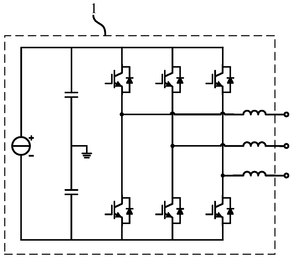
[0038] The current generator is used to generate the test current, and the...


PUM


Abstract

The invention provides a testing circuit for cascaded converter multi-submodule multi-working condition simulation. The circuit includes a current generator and a submodule system; the current generator is used for generating testing current and includes a three-port converter and corresponding filters; the submodule system includes an upper bridge arm testing unit module and a lower bridge arm testing unit module which are in series connection; the upper bridge arm testing unit module includes multiple upper bridge arm testing units in series connection; the lower bridge arm testing unit module includes multiple lower bridge arm testing units in series connection; each testing unit includes two detected submodules in reverse series connection; and the upper and lower bridge arm testing units receive the testing current generated by the current generator and output voltage signals, or the voltage signals and current signals of the detected submodules in each testing unit to external. The circuit can realize the operation working condition simulation of any submodules of a cascaded converter, and realize the simultaneous testing of the multiple submodules under multiple working conditions, so that testing costs can be saved, and testing efficiency can be enhanced.

Description

technical field [0001] The invention relates to the technical field of power electronics, in particular to a test circuit for simulating multiple sub-modules and multiple working conditions of a cascaded converter. Background technique [0002] The cascaded converter is composed of cascaded sub-modules, and its basic structure makes the system easy to expand, and has a good prospect in high-voltage and large-capacity operating scenarios. Since the operating characteristics of the sub-module are closely related to the converter, in order to ensure the long-term reliable operation of the converter, it is of great significance to test the operating characteristics of the sub-module in actual working conditions. However, the traditional cascaded converter sub-module test method needs to build a relatively complete cascaded converter system, and its limitations are: [0003] 1) Building the system brings high time and economic costs; [0004] 2) Great power loss during the test...

Claims


Application Information

Patent Timeline
Patent Type & Authority Applications(China)
IPC IPC(8): G01R31/00G01R1/28G01R1/30
Inventor 马柯姜山
Owner SHANGHAI JIAO TONG UNIV
Learn More