A blind adaptive beam forming algorithm

A technology of beamforming and blind self-adaptation, applied in space transmit diversity, electrical components, transmission systems, etc., can solve complex channel estimation, increase the complexity of radio frequency identification systems, etc., achieve simple operation process, enhance transmission stability, The effect of improving efficiency

Inactive Publication Date: 2019-05-03
SHENZHEN INST OF ADVANCED TECH CHINESE ACAD OF SCI
View PDF0 Cites 3 Cited by
  • Summary
  • Abstract
  • Description
  • Claims
  • Application Information

AI Technical Summary

Problems solved by technology

Although this can achieve the best effect of the beamforming algorithm, at the same time, this method introduces complex channel estimation, so it will greatly increase the complexity of the RFID system

Method used

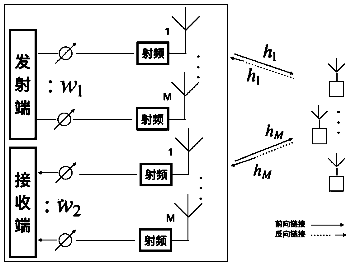
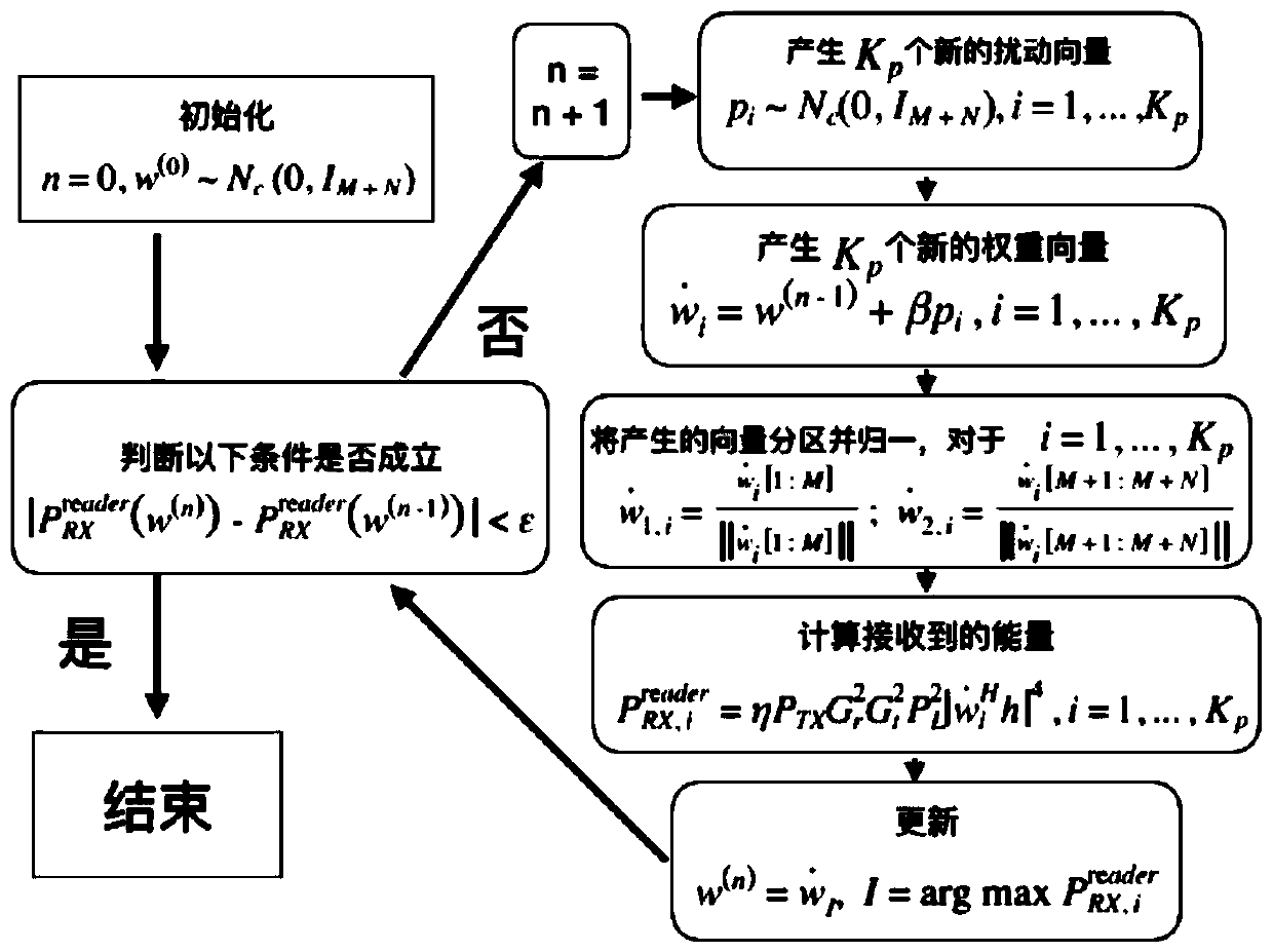
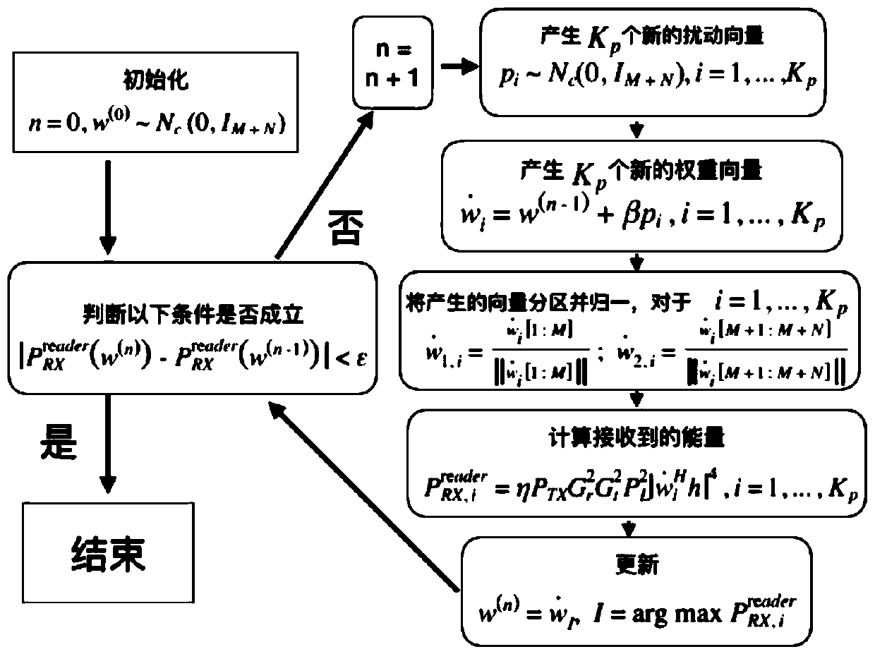

Image

  • A blind adaptive beam forming algorithm
  • A blind adaptive beam forming algorithm
  • A blind adaptive beam forming algorithm

Examples


Embodiment Construction

[0035] In order to make the purpose, technical solutions and advantages of the embodiments of the present invention clearer, the technical solutions in the embodiments of the present invention will be clearly and completely described below in conjunction with the accompanying drawings in the embodiments of the present invention. Obviously, the described embodiments It is some embodiments of the present invention, but not all of them. Based on the implementation manners in the present invention, all other implementation manners obtained by persons of ordinary skill in the art without creative efforts fall within the protection scope of the present invention. Accordingly, the following detailed description of the embodiments of the invention provided in the accompanying drawings is not intended to limit the scope of the claimed invention, but merely represents selected embodiments of the invention. Based on the implementation manners in the present invention, all other implement...


PUM


Abstract

The invention relates to a blind adaptive beam forming algorithm, in particular to a blind adaptive beam forming algorithm applied to a half-duplex passive ultrahigh frequency radio frequency identification system. The algorithm creatively provides an iteration idea, so that compared with an original method, the necessity and complexity of channel estimation are reduced, the operation process is simple, the system operation cost is greatly reduced, and meanwhile the efficiency is improved.

Description

technical field [0001] The invention relates to a blind adaptive beamforming algorithm applied to a half-duplex passive UHF radio frequency identification system. Background technique [0002] At present, UHF radio frequency identification technology has received widespread attention. This technology uses a frequency of 860-960 MHz and can be applied in many fields, such as: supply chain management, logistics support system, automatic toll collection system, intelligent transportation system, etc. etc., its recognition efficiency is higher than traditional barcode system. [0003] Passive UHF RFID systems (PassiveUHF RFIDsystems) usually include several modules: readers, tags and data processing centers. Among them, there are usually multiple antennas in the reader, and there is usually only one antenna in the tag. In this system, the tag is not powered by a battery, but works by absorbing the energy carried by the electromagnetic field emitted by the transmitting antenna ...

Claims


Application Information

Patent Timeline
Patent Type & Authority Applications(China)
IPC IPC(8): H04B7/06H04B5/00H04L5/16
CPCH04B5/00H04B7/06H04L5/16
Inventor 刘竞升王晓东
Owner SHENZHEN INST OF ADVANCED TECH CHINESE ACAD OF SCI
Why Eureka
Try Eureka