A method and a device for optimizing an antenna azimuth angle

A technology of antenna azimuth and optimization method, which is applied in the field of communication, can solve the problem of high operation and maintenance costs, and achieve the effect of reducing costs

Active Publication Date: 2019-05-03
CHINA UNITED NETWORK COMM GRP CO LTD
View PDF8 Cites 13 Cited by
  • Summary
  • Abstract
  • Description
  • Claims
  • Application Information

AI Technical Summary

Problems solved by technology

[0004] The embodiments of the present invention provide a method and device for optimizing the antenna azimuth angle, which solves the problem of relying on drive test data or statistical data combined with maps to analyze the coverage direction, or going to the site to investigate the coverage angle when optimizing the antenna azimuth angle in the prior art. Or rely on the location of user complaints to adjust the coverage, resulting in a high cost of operation and maintenance

Method used


Image

  • A method and a device for optimizing an antenna azimuth angle
  • A method and a device for optimizing an antenna azimuth angle
  • A method and a device for optimizing an antenna azimuth angle

Examples


Embodiment 1

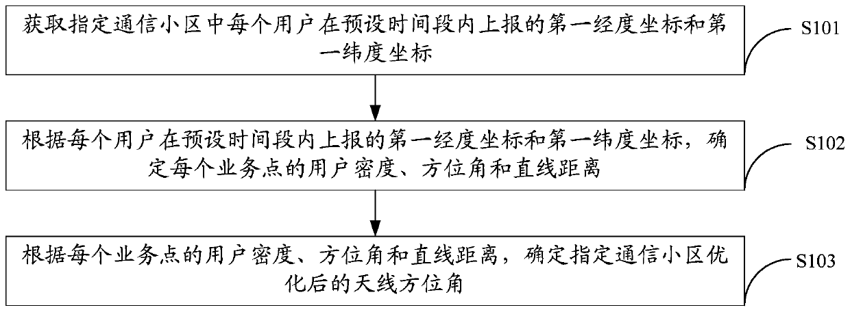
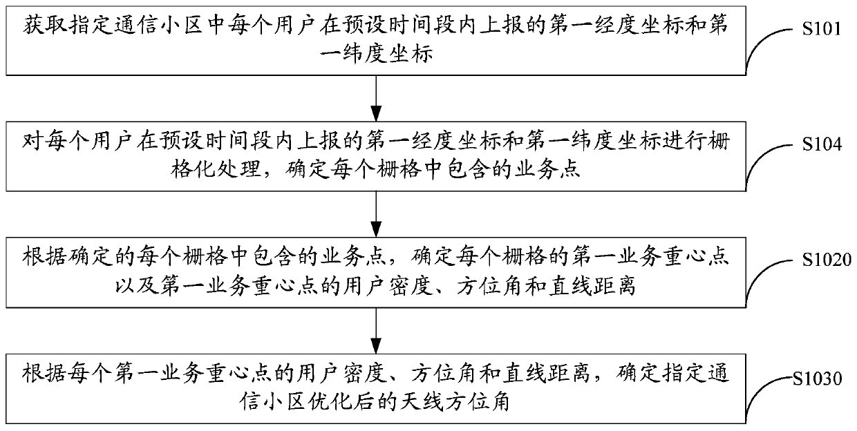
[0050] Embodiments of the present invention provide a method for optimizing an antenna azimuth, such as figure 2 Shown include:

[0051] S101. Obtain a first longitude coordinate and a first latitude coordinate reported by each user in a designated communication cell within a preset time period.

[0052] It should be noted that in practical applications, the measurement report (English full name: MeasureReport, abbreviated: MR) based on the Assisted Global Positioning System (English full name: Assisted Global Positioning System, abbreviated: AGPS) already contains the longitude and latitude reported by the user. Location information no longer needs to be positioned by algorithms in the later stage. The user-level measurement report MR can be periodically collected from the network management system and stored in the local server; therefore, the data such as measurement reports and antenna parameters can be used for automatic calculation, thereby reducing the time for manual...

Embodiment 2

[0124] An embodiment of the present invention provides an antenna azimuth optimization device 10, such as Figure 12 Shown include:

[0125] The obtaining unit 101 is configured to obtain a first longitude coordinate and a first latitude coordinate reported by each user in a designated communication cell within a preset time period.

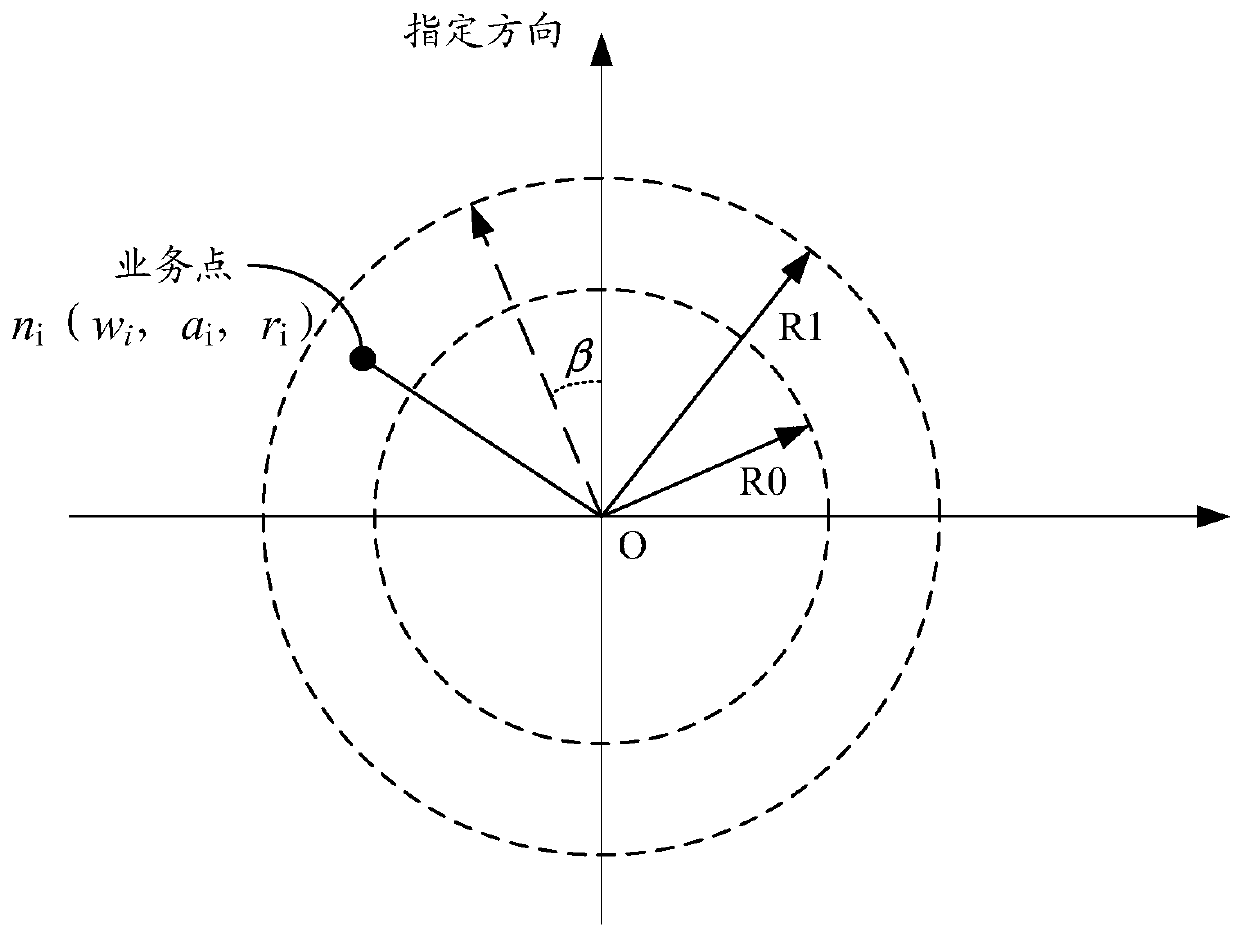
[0126] The processing unit 102 is configured to determine the user density, azimuth and straight-line distance of each service point according to the first longitude coordinates and first latitude coordinates reported by each user within a preset time period acquired by the acquisition unit 101; , each service point corresponds to a second longitude coordinate and a second latitude coordinate, and the service point contains at least one user, and the user density is equal to the first total number of users contained in the service point and the users served by the designated communication cell within a preset time period The ratio of the second ...


PUM


Abstract

The embodiment of the invention provides a method and a device for optimizing an antenna azimuth angle, relates to the technical field of communication, and solves the problem that in the prior art,when the antenna azimuth angle is optimized, the operation and maintenance cost is high due to the fact that the coverage direction is analyzed by relying on drive test data or statistical data in combination with a map, or the coverage angle is explored on site, or a user complaint position is used for coverage adjustment. The method comprises the following steps: acquiring a first longitude coordinate and a first latitude coordinate reported by each user in an appointed communication cell within a preset time period; Determining the user density, the azimuth angle and the linear distance ofeach service point according to the longitude coordinates and the latitude coordinates reported by each user in the preset time period; And determining the optimized antenna azimuth angle of the specified communication cell according to the user density, the azimuth angle and the linear distance of each service point.

Description

technical field [0001] The invention relates to the technical field of communications, in particular to a method and device for optimizing an antenna azimuth angle. Background technique [0002] With the continuous iterative update of communication services and the increasing demand for networks, how to maximize resource efficiency, improve network value, and thereby improve user perception is the focus of every operator. For network optimization, it is becoming more and more important to improve user perception in densely serviced areas covered by cells, but traditional coverage optimization often relies on drive test data or statistical data combined with maps to analyze coverage directions, or to investigate coverage angles on site, or Relying on the location of user complaints to adjust coverage, these traditional methods are not only time-consuming, laborious and expensive, but also often solve problems after they occur, resulting in poor user experience. [0003] It c...

Claims


Application Information

Patent Timeline
Patent Type & Authority Applications(China)
IPC IPC(8): H04W24/02H04W64/00
Inventor 郭建川陈刚何春霞黄智勇孔祥斌廖江钟豫粤黄炜俞敏范娟
Owner CHINA UNITED NETWORK COMM GRP CO LTD
Why Eureka
Try Eureka