Supercharge Your Innovation With Domain-Expert AI Agents!

Objective with a fixed focal length and a constant structural length for autofocus applications

A lens, focal length technology, applied in the field of lens/objective lens

Active Publication Date: 2019-05-03
莱卡照相机股份公司
View PDF12 Cites 0 Cited by
  • Summary
  • Abstract
  • Description
  • Claims
  • Application Information

AI Technical Summary

Problems solved by technology

However, if high imaging performance should be achieved, complex and expensive lens structures with a large number of different lenses are required

Method used


Image

  • Objective with a fixed focal length and a constant structural length for autofocus applications
  • Objective with a fixed focal length and a constant structural length for autofocus applications
  • Objective with a fixed focal length and a constant structural length for autofocus applications

Examples


Embodiment Construction

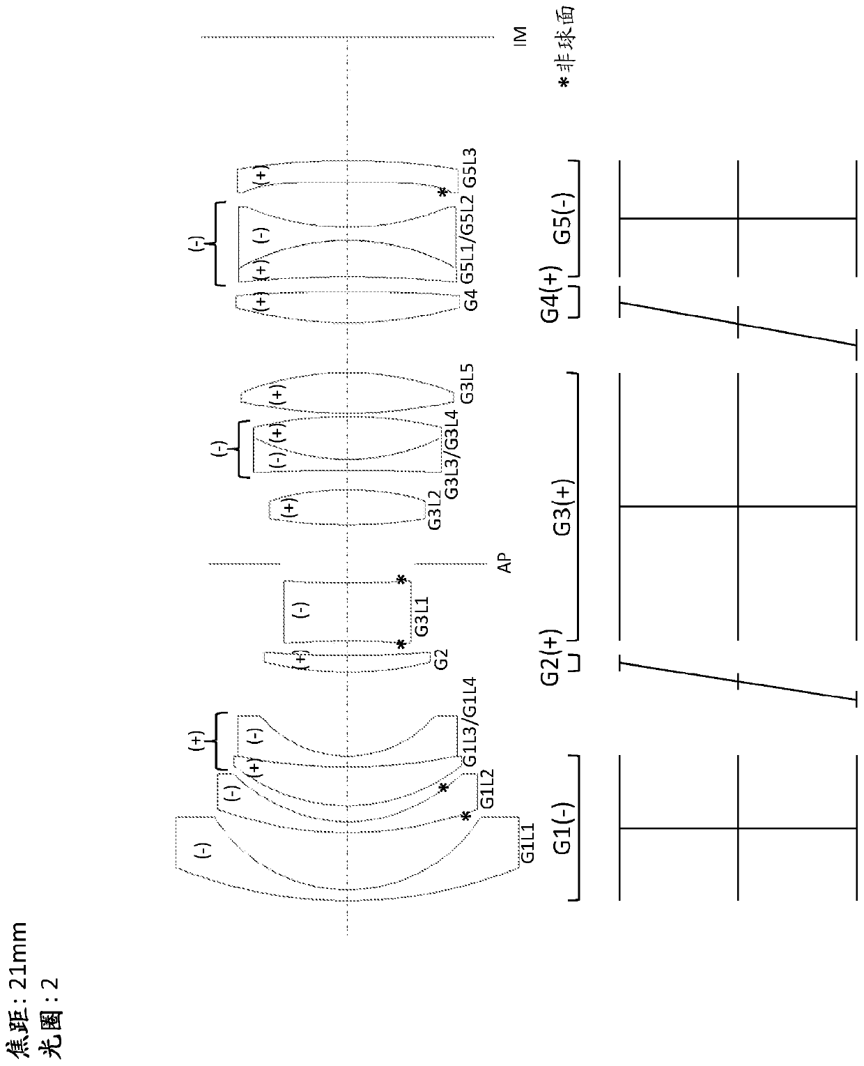
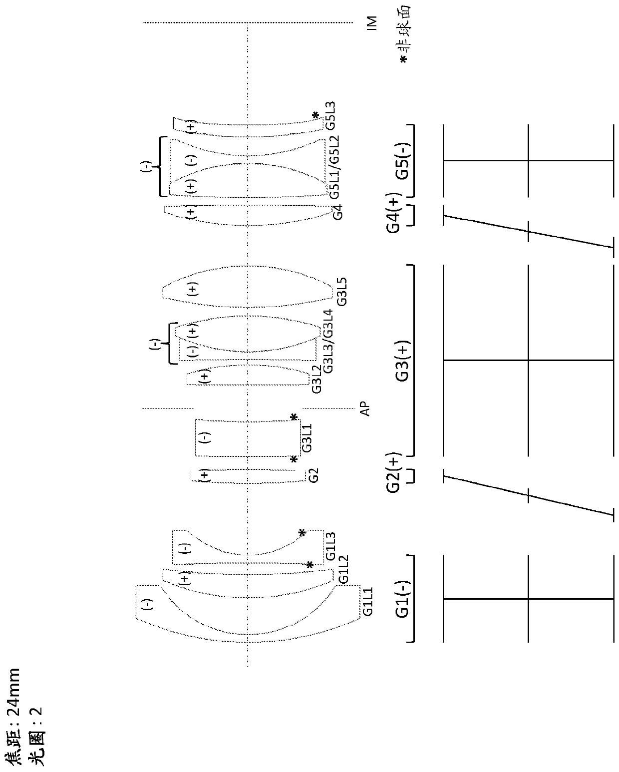
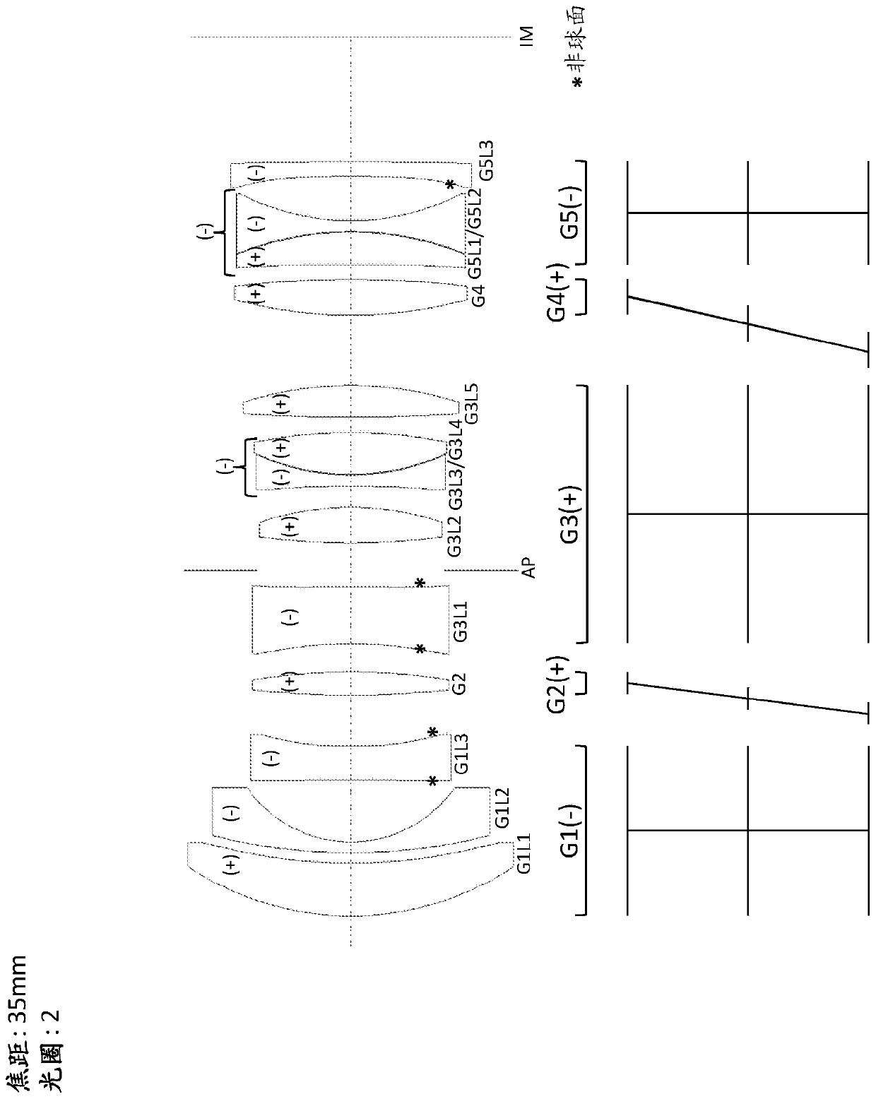
[0054] The path of movement of the corresponding lens group during the focusing process is shown in the lens section of the drawing. Horizontal lines indicate the positions of lens groups G1, G2, G3, G4 and G5. The upper horizontal line among the horizontal lines indicates the position when focusing to infinity, the lower horizontal line indicates the position when focusing on the shortest object distance, and the middle horizontal line indicates the position when focusing to the middle. The vertical lines correspond to the fixed lens groups G1, G3 and G5, and the oblique lines correspond to the movable focusing groups G2 and G4.

[0055] for in figure 1 In the lens with a focal length of 21 mm shown in , the first lens group G1 has a negative power convex-concave lens G1L1 in which the concave (inner) radius of curvature is significantly smaller than the convex (outer) radius of curvature. This results in a geometrically measurably thin lens center relative to the material ...


PUM


Abstract

The invention relates to an objective with a fixed focal length, consisting of five lens groups. Three lens groups (G1, G2 G5) are stationary, and two lens groups (G2, G4) are mounted in a movable manner along an optical axis for focusing purposes. A first front lens group (G1), when seen from the object side, is stationary; a second lens group in the form of a front focusing group (G2) can be moved; a third lens group in the form of a central group (G3) is stationary, said lens group containing a stationary iris diaphragm (AP) with an adjustable opening; a fourth lens group in the form of a rear focusing group (G4) can be moved; and a fifth rear lens group (G5) is arranged in a lens barrel in a stationary manner relative to an imaging plane (IM). Both the front focusing group (G2) as wellas the rear focusing group (G4) are moved together relative to each other and to the stationary lens group (G1, G3, G5) in order to focus the objective on objects at different object distances, and the front lens group (G1) and the rear lens group (G5) have a negative refractive power.

Description

technical field [0001] The invention relates to a fixed focal length interchangeable lens / objective according to the preamble of claim 1 . Background technique [0002] Such lenses for photographic recording purposes are known from analog photography and are likewise used in digital photography. Increasingly, digital cameras no longer have mirrors that can be swung into and out of the shooting light path (the mirrors shift the object field to be photographed into the viewfinder via prisms for focusing purposes and for selection of image parts ), but by means of a permanent capture with the camera sensor and the image is selected by means of the object area thus obtained and displayed on the display on the rear of the camera or by means of an electronic viewfinder. The focusing of the lens is carried out automatically by means of the electronic autofocus signal and the corresponding activation of the focusing elements in the lens. Usually, in order to produce good imaging p...

Claims


Application Information

Patent Timeline
IPC IPC(8): G02B27/00G02B13/04
CPCG02B27/0075G02B13/04G02B9/60G02B13/18G02B9/64G02B13/0045G02B13/006
Inventor D·斯图布尔S·卡曼斯
Owner 莱卡照相机股份公司
Features
  • R&D
  • Intellectual Property
  • Life Sciences
  • Materials
  • Tech Scout
  • Unparalleled Data Quality
  • Higher Quality Content
  • 60% Fewer Hallucinations
Learn More