sheet music stand
A technology for music scores and support panels, applied in the field of music score stands, to achieve the effects of simple components, low manufacturing costs, and easy application of push rods
- Summary
- Abstract
- Description
- Claims
- Application Information
AI Technical Summary
Problems solved by technology
Method used
Image
Examples
Embodiment 1
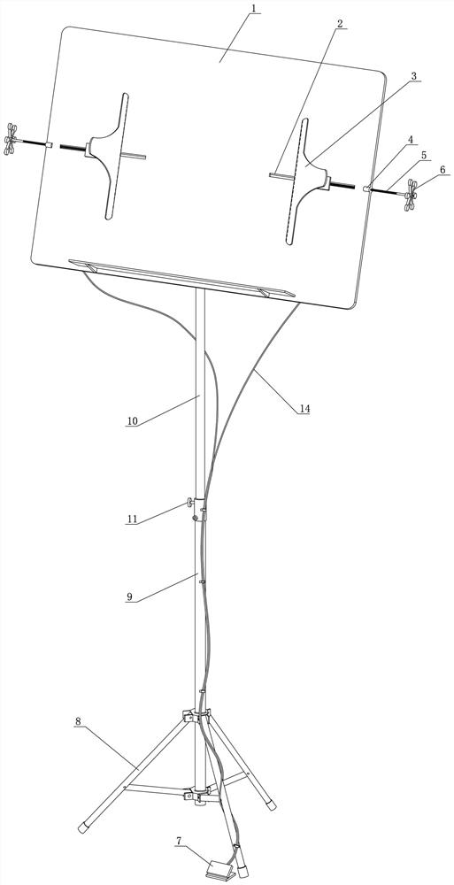
[0021] Embodiment 1: as figure 1 As shown in the musical score stand, the back of the support panel 1 is installed on the upper end of the support through a fixture, and the support is a foldable telescopic frame, including a foldable bottom frame 8 and a support rod, and the support rod includes a sleeve 149 and a sleeve rod 10 set together. Its height is fixed by locking pin 11. The structure is basically the same as that of the traditional musical score stand. What is different from the traditional music stand is that this embodiment adopts an improved structure of the support panel 1 and a special pressing part.
[0022] Such as figure 1 Among them, the support panel 1 can be a planar body, or a hollow structure, or a frame structure. But the two sides of the middle part of the support panel 1 are symmetrically provided with transverse slide grooves 2 . And a platen driving mechanism 3 is installed in each horizontal slide groove 2 .
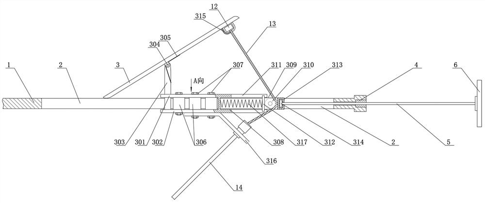
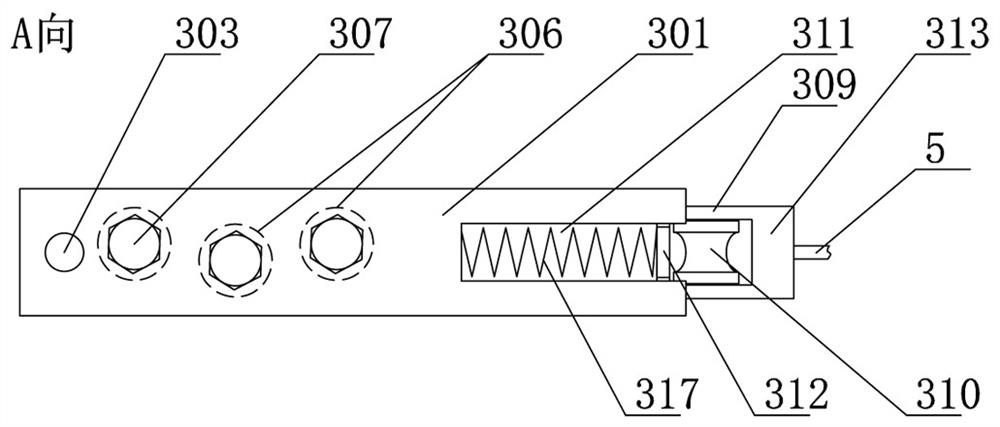
[0023] Such as figure 2 As sho...
Embodiment 2
[0033] Embodiment 2: Embodiment 1 provides the pressing and loosening functions for the fixed form of the music score page. When the size of the music score changes, this embodiment can be based on Embodiment 1, and the upper plate 301 and the lower plate The slide block 309 at the rear end between 302 is provided with a fixed sleeve 313, and the fixed sleeve 313 is equipped with a rotating block 314, and the rotating block 314 is fixedly connected to the screw rod 5, and the screw sleeve 4 is installed on the screw rod 5, and an adjustment knob is installed at the end of the screw rod 5 6. The screw sleeve 4 is fixed on the support panel 1 at the end of the horizontal chute 2, and the screw rod 5 is located in the horizontal chute 2. After the adjustment knob 6 is turned, the horizontal position of the platen driving mechanism 3 can be changed, that is, the distance between the platen driving mechanisms 3 on both sides can be changed, so that it is suitable for pressing pages ...
PUM
 Abstract
Description
Claims
Application Information
 - R&D
- Intellectual Property
- Life Sciences
- Materials
- Tech Scout
- Unparalleled Data Quality
- Higher Quality Content
- 60% Fewer Hallucinations
Browse by: Latest US Patents, China's latest patents, Technical Efficacy Thesaurus, Application Domain, Technology Topic, Popular Technical Reports.
© 2025 PatSnap. All rights reserved.Legal|Privacy policy|Modern Slavery Act Transparency Statement|Sitemap|About US| Contact US: help@patsnap.com


