
Annular workpiece polishing device

A technology of polishing device and annular workpiece, which is applied in the directions of grinding/polishing safety device, grinding workpiece support, grinding driving device, etc., can solve the problem of unfavorable batch grinding and polishing of annular workpiece, and the polishing quality cannot be guaranteed and affected. The service life of components and other issues, to achieve the effect of convenient and unified recycling, high degree of automation, and extended service life

Inactive Publication Date: 2020-09-08
LANZHOU UNIVERSITY OF TECHNOLOGY
View PDF9 Cites 6 Cited by
  • Summary
  • Abstract
  • Description
  • Claims
  • Application Information

AI Technical Summary

Problems solved by technology

[0002] Ring-shaped workpieces, such as the inner and outer rings of bearings, iron rings, sealing rings, ferrules and other components, need to be polished on the inner and outer surfaces after production to make the surface smooth. However, traditional polishing When the equipment is polished, it is first necessary to reliably fix the ring-shaped fittings on the shelf, and polish the outer peripheral wall of the ring-shaped fittings with a polishing wheel. The operation is cumbersome, the polishing efficiency is slow, and the polishing quality cannot be guaranteed.
[0003] The existing polishing equipment has a low degree of automation and requires a lot of manual operation to fix the inner surface to polish the outer surface, and then fix the outer surface to polish the inner surface, which is not conducive to batch grinding and polishing of ring-shaped workpieces
[0004] At the same time, some debris will be generated during polishing. If it cannot be cleaned in time, it will affect the inspection of the operator and the service life of each component. If it can be recycled, it can also reduce the cost. Therefore, a ring-shaped workpiece that can meet different sizes is required. A polishing device for fast grinding and polishing of the inner and outer surfaces with a high degree of automatic paste

Method used


Image

  • Annular workpiece polishing device
  • Annular workpiece polishing device
  • Annular workpiece polishing device

Examples


Embodiment Construction

[0026] The technical solution of this patent will be further described in detail below in conjunction with specific embodiments.

[0027] Embodiments of the present patent are described in detail below, examples of which are shown in the drawings, wherein the same or similar reference numerals designate the same or similar elements or elements having the same or similar functions throughout. The embodiments described below by referring to the figures are exemplary and are only used for explaining the patent, and should not be construed as limiting the patent.

[0028] In the description of this patent, it is to be understood that the terms "center", "upper", "lower", "front", "rear", "left", "right", "vertical", "horizontal", The orientation or positional relationship indicated by "top", "bottom", "inner", "outer", etc. is based on the orientation or positional relationship shown in the drawings, and is only for the convenience of describing this patent and simplifying the des...


PUM


Abstract

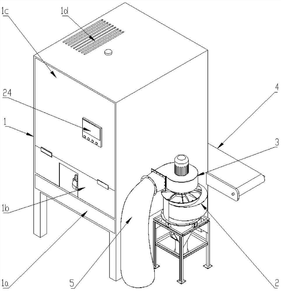
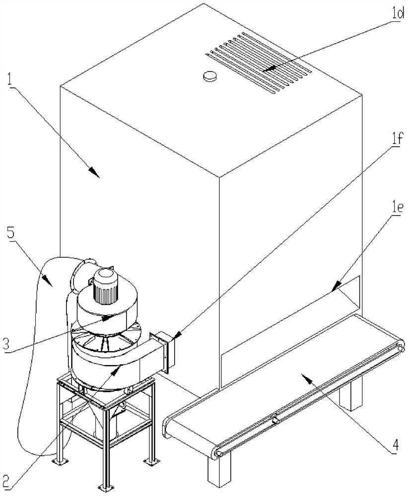
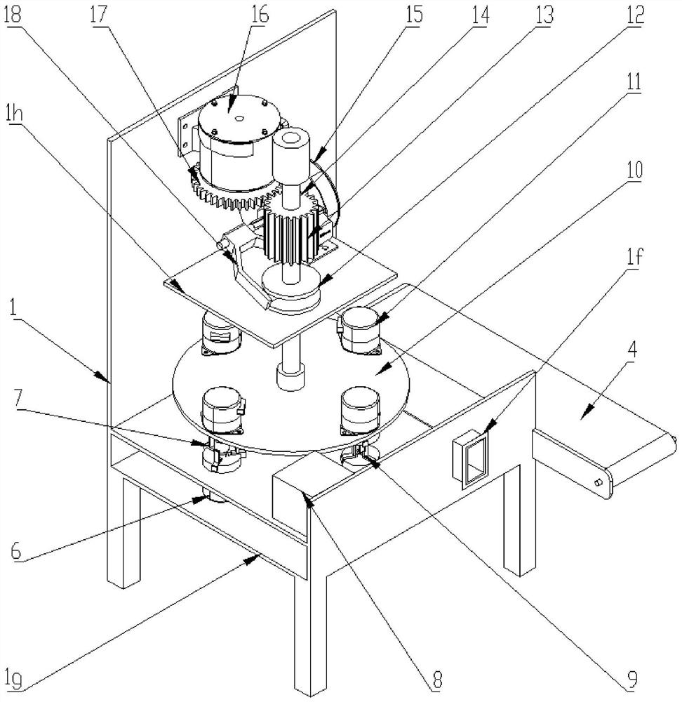
The invention provides an annular workpiece polishing device, belongs to the technical field of polishing machinery, and is used for solving the problems of low automatic degree and low efficiency onpolishing upper and lower surfaces of inside and outside of an annular workpiece. The annular workpiece polishing device comprises a tank, wherein triangular supporting claws I are arranged on outputshafts of two lower motors opposite to each other; a triangular clamping claw is arranged on an output shaft of the other lower motor; a power assembly is arranged in a polishing chamber; a rotating disk is fixed to the lower end of a driving shaft; four upper motors uniformly distributed circumferentially are fixed to the upper end of the rotating disk; triangular supporting claws II are arrangedon output shafts of the two upper motors opposite to each other; an inner polishing grind head and an outer polishing sleeve head are detachably arranged on output shafts of the other two upper motors opposite to each other; a chip removal pipe is connected with a chip collecting assembly; and a discharging crawler belt is arranged on the rear side of the tank. The annular workpiece polishing device provided by the invention is wide in application range, capable of quickly polishing the upper and lower surfaces of inside and outside of the annular workpiece, high in automatic degree, and beneficial to conveniently recovering ground and polished chips, has air cooling and temperature reducing functions, and is beneficial to prolonging the service life.

Description

technical field [0001] The invention belongs to the technical field of polishing machines, and relates to a polishing device, in particular to a ring-shaped workpiece polishing device. Background technique [0002] Ring-shaped workpieces, such as the inner and outer rings of bearings, iron rings, sealing rings, ferrules and other components, need to be polished on the inner and outer surfaces after production to make the surface smooth. However, traditional polishing When the equipment is polished, it is first necessary to reliably fix the ring-shaped fittings on the rest seat, and polish the outer peripheral wall of the ring-shaped fittings with a polishing wheel. The operation is cumbersome, the polishing efficiency is slow, and the polishing quality cannot be guaranteed. [0003] The existing polishing equipment has a low degree of automation and requires a lot of manual operation to fix the inner surface to polish the outer surface, and then fix the outer surface to poli...

Claims


Application Information

Patent Timeline
Patent Type & Authority Applications(China)
IPC IPC(8): B24B29/02B24B27/00B24B55/02B24B55/06B24B41/00B24B47/12B24B41/06
CPCB24B27/0076B24B29/02B24B41/005B24B41/067B24B47/12B24B55/02B24B55/06
Inventor 张书涛苏建宁周爱民欧阳晋焱
Owner LANZHOU UNIVERSITY OF TECHNOLOGY
Learn More