Concrete mixing device for water conservancy engineering

A technology of water conservancy projects and mixing devices, which is applied in the direction of cement mixing devices, clay preparation devices, chemical instruments and methods, etc., can solve problems such as poor performance, large impact area, uneven mixing, etc., and achieve uniform and stable concrete, large Three-dimensional effect of stirring driving force and motion trajectory

Inactive Publication Date: 2020-09-01
湖南佳伦建筑工程有限公司
View PDF7 Cites 0 Cited by
  • Summary
  • Abstract
  • Description
  • Claims
  • Application Information

AI Technical Summary

Problems solved by technology

[0002] Concrete is used in all kinds of civil engineering, and some special engineering types are required to have unusual performance. In water conservancy projects, because field work is often required, and the transportation is extremely inconvenient, if the concrete is directly transported from the mixing station Not only is it time-consuming, but it is also difficult to transport. Therefore, in many cases, direct delivery from the mixing station is not suitable for some small and medium-sized water conservancy projects. The area involved is large, and the requirements for concrete are naturally high. The long-distance transportation makes the concrete easy to fail, and the closer it is to its final setting time, the poorer the performance. Therefore, on-site mixing is required.
At present, the equipment for mixing concrete on site is usually as follows: figure 1 The stirring equipment shown is a cylinder with an opening facing upwards, and a rotatable stirring shaft is coaxially installed inside, and the stirring shaft is provided with a circle of blades in the radial direction for circular stirring. Concrete rotates continuously in one direction, and the mixing is easy to be uneven, and due to its own weight, the concrete will naturally settle down, especially the aggregate, resulting in more aggregate at the bottom of the mixing tank, and the upper and lower concrete are actually stratified to a certain extent. Phenomenon, which greatly affects the quality of concrete preparation, resulting in the unqualified proportioning accuracy of some concrete

Method used


Image

  • Concrete mixing device for water conservancy engineering
  • Concrete mixing device for water conservancy engineering
  • Concrete mixing device for water conservancy engineering

Examples


Embodiment Construction

[0014] The implementation of the present invention will be illustrated by specific specific examples below, and those skilled in the art can easily understand other advantages and effects of the present invention from the contents disclosed in this specification.

[0015] Below in conjunction with accompanying drawing and embodiment the present invention will be further described:

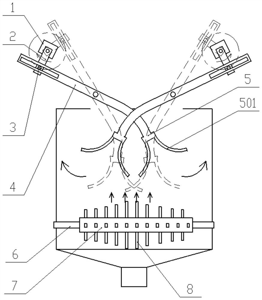
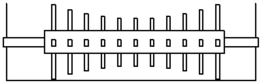
[0016] like figure 1 Shown in -2, a concrete mixing device for water conservancy projects, it specifically includes a mixing bucket for mixing various raw materials of concrete, the mixing bucket is a vertical mixing bucket with an opening facing upwards, and a mixing bucket for mixing is installed in the mixing bucket The stirring part, the mixing barrel is a cuboid structure, and its opening is arranged along its length direction; the stirring part includes a digging stirring part and a rotating part from top to bottom, and the specific structure of these parts is as follows:

[0017] For the di...


PUM


Abstract

The invention discloses a concrete mixing device used for hydraulic engineering. The concrete mixing device comprises a mixing barrel. The mixing barrel is a vertical mixing barrel with an opening facing upwards. A mixing component used for mixing is mounted in the mixing barrel. The mixing barrel is of a cuboid structure. A digging mixing portion comprises a plurality of digging mechanisms. All the digging mechanisms are arranged in a row in the length direction of the opening of the mixing barrel, and the adjacent digging mechanisms are arranged in a staggered mode in the front-back and left-right directions. Each digging mechanism comprises a rotary arm and a digging arm which are driven by a motor. The rotating directions of the motors on every two adjacent digging mechanisms are opposite. A rotary component is mounted under turning portions of every two adjacent digging mechanisms, wherein four rows of mixing blades are mounted at four quadrantal points of a section circle of a drum correspondingly, and each row of mixing blades is arranged in the radial direction of the drum. According to the concrete mixing device used for hydraulic engineering, mixing is uniform, the concrete mixing quality is greatly improved, and the applicability of the concrete mixing device particularly to concrete preparation of medium hydraulic projects is higher.

Description

technical field [0001] The invention belongs to the technical field of hydraulic engineering, in particular to a concrete preparation device used in hydraulic engineering. Background technique [0002] Concrete is used in all kinds of civil engineering, and some special engineering types are required to have unusual performance. In water conservancy projects, because field work is often required, and the transportation is extremely inconvenient, if the concrete is directly transported from the mixing station Not only is it time-consuming, but it is also difficult to transport. Therefore, in many cases, direct delivery from the mixing station is not suitable for some small and medium-sized water conservancy projects. The area involved is large, and the requirements for concrete are naturally high. The long-distance transportation makes the concrete easy to fail, and the closer to its final setting time, the poorer the performance, so it needs to be mixed on site. At present,...

Claims


Application Information

Patent Timeline
Patent Type & Authority Patents(China)
IPC IPC(8): B28C5/14
Inventor 王娟许柯刘海玲冯少立封金萍穆克迪王孟云汪海燕
Owner 湖南佳伦建筑工程有限公司
Why Eureka
Try Eureka