Eureka AIR delivers breakthrough ideas for toughest innovation challenges, trusted by R&D personnel around the world.

A method for phase unwrapping and demodulating a low-reflectivity F-P sensor

A technology of phase unwrapping and low reflectivity, which is applied in the direction of using optical devices to transmit sensing components, etc., can solve the problems of high cost and large filtering loss, and achieve the effect of low cost, small amount of calculation, and accurate demodulation results

Active Publication Date: 2019-05-07
CHENGDU KAITIAN ELECTRONICS
View PDF6 Cites 0 Cited by
  • Summary
  • Abstract
  • Description
  • Claims
  • Application Information

AI Technical Summary

Problems solved by technology

This demodulation method has the advantages of high sensitivity, high light energy utilization, simple operation, wide FFP tuning range, and good system stability. It is suitable for wavelength shift detection technology in engineering applications, but the high-precision FFP filter costs Higher, and the filter loss is larger

Method used


Image

  • A method for phase unwrapping and demodulating a low-reflectivity F-P sensor
  • A method for phase unwrapping and demodulating a low-reflectivity F-P sensor
  • A method for phase unwrapping and demodulating a low-reflectivity F-P sensor

Examples


Embodiment Construction

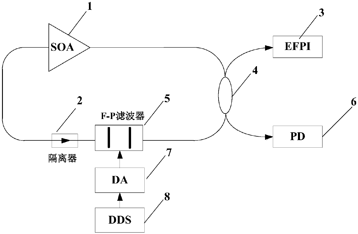
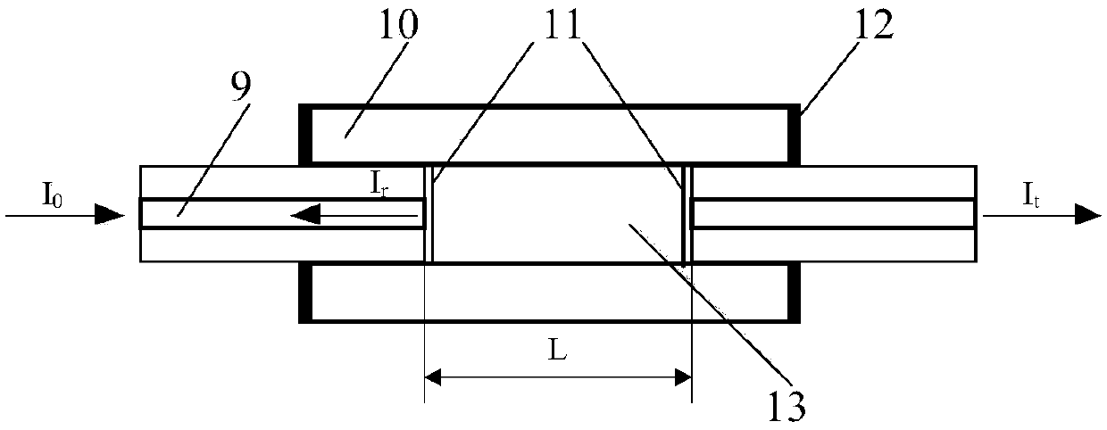
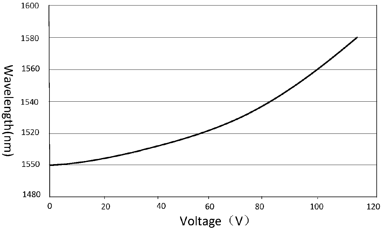
[0016] refer to figure 1 , figure 2 . According to the present invention, at first, the semiconductor optical amplifier SOA1, the optical isolator 2, the coupler 4 and the F-P filter 5 are connected in series to form a closed-loop loop, and the EFPI sensor 3, the phototransistor PD6, and the EFPI sensor are connected at the two ends of the coupler 4 3 is the external cavity type F-P interferometer EFPI sensor. The F-P filter 5 forms a demodulator through a digital-to-analog converter DA7 in series with a digital frequency synthesizer DDS 8; in the demodulator, according to the voltage-central wavelength function of the F-P filter 5, the F-P filter 5 scanning correction function is derived, Then the digital frequency synthesizer DDS8 outputs the scanning signal according to the correction function, and the F-P filter 5 outputs the narrow-band scanning light according to the corrected function, and the narrow-band scanning light scans the EFPI sensor 3 and the reference F-P e...


PUM


Abstract

The invention discloses a method for phase unwrapping and demodulating a low-reflectivity F-P sensor, and aims to provide a phase unwrapping demodulation low-reflectivity F-which is accurate in demodulation result, small in calculated amount and low in cost. The method is realized through the following technical scheme: in a demodulator, according to a voltage-central wavelength function of a F-Pfilter, a F-P filter scan correction function is derived, and a scanning signal is output according to the correction function through a DDS; the F-P filter outputs narrow-band scanning light according to the corrected function, and the narrow-band scanning light simultaneously scans an EFPI sensor and a reference F-p etalon through a coupler, the reference F-P etalon performs phase unwrapping ona linearized spectrum obtained through sampling according to inverse cosine, phase splicing is carried out at the positions of -pi and pi, linear fitting is carried out after a phase straight line isspliced, the cavity length of the EFPI sensor is calculated through the slope, and demodulation of the low-reflectivity FP sensor is realized.

Description

technical field [0001] The invention relates to a low reflectivity F-P sensor demodulation method used in the field of optical fiber sensing. Background technique [0002] In the light-transmitting fiber optic sensor, the optical fiber is only used as the light-transmitting medium to transmit the optical signal modulated by the external signal to the optical detector, extract the external signal from the light wave and perform data processing as required, that is, demodulation . The fiber optic F-P sensor is developed from the F-P interferometer, and its resonant cavity is composed of a light-guiding medium such as air or optical fiber with a specific length. The transmission loss of light in the F-P cavity is large, which has a great impact on the quality of the sensor output signal, which is not conducive to the multiplexing of the sensor. In order to make the output signal of the sensor within the long range of its working cavity have the best possible contrast as a who...

Claims


Application Information

Patent Timeline
Patent Type & Authority Applications(China)
IPC IPC(8): G01D5/26
Inventor 代勇波任清周力杰李翔
Owner CHENGDU KAITIAN ELECTRONICS
Why Eureka
Eureka Blog
Learn More