System for monitoring wire

A wire and visible light technology, applied in the field of communication, can solve the problems of wire loss, damage, high cost and so on

Inactive Publication Date: 2019-05-07
西安宇斌信息科技有限公司
View PDF0 Cites 0 Cited by
  • Summary
  • Abstract
  • Description
  • Claims
  • Application Information

AI Technical Summary

Problems solved by technology

[0004] In order to solve the above problems, the present invention provides a system for monitoring wires, which effectively avoids the defects that the prior art cannot completely solve the problems of wire loss, damage, and high cost in various environments.

Method used


Image

  • System for monitoring wire
  • System for monitoring wire

Examples


Embodiment Construction

[0026] The present invention will be further described below in conjunction with examples.

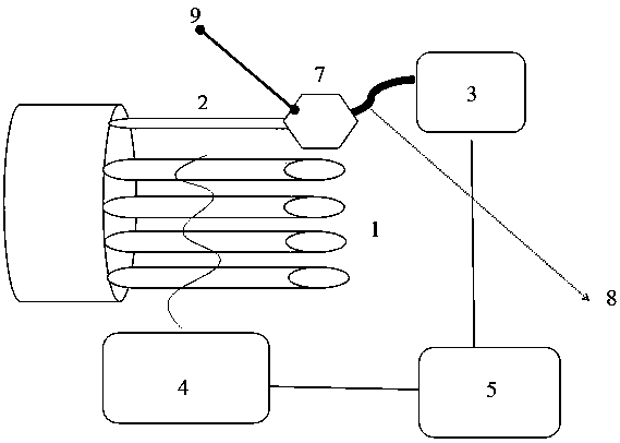
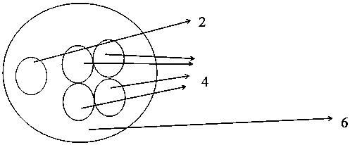
[0027] Such as Figure 1-Figure 2 As shown, the system for monitoring wires includes wires, the wires include a wire body 1 and a visible light path 2, and the wire body 1 and the visible light path 2 are wrapped by a coating layer; the two ends of the wires are reserved with visible light path interfaces , the visible light path interface reserved at both ends of the wire is respectively connected to the two ends of the visible light path 2; the visible light path 2 is connected to the optical port of PUES3 through the visible light path interface; the wire main body 1 is connected to the power transmission The transmitter 4 is connected, and the power transmitter 4 is electrically connected to the processor 5; the processor 5 is connected to the communication interface of the PUES3. The visible light channel 2 is a single-core single-mode visible light channel or a multi-core single...


PUM


Abstract

The invention discloses a system for monitoring a wire. A visible light path interface is an FC visible light path interface; the visible light path interface is connected with the optical port of thePUES3 through a visible light path flange; the visible light path flange is grounded through a grounding wire, and grounding of the grounding wire meets the actual load pressure grounding standard ofthe wire; the electric quantity transmitter is matched with the actual load value of the current wire; and the processor has a function of receiving the current value acquired by the electric quantity transmitter. The defects that in the prior art, wire loss and damage in various environments cannot be thoroughly overcome, and the manufacturing cost is high are overcome.

Description

technical field [0001] The invention relates to the technical field of communication, in particular to a system for monitoring wires. Background technique [0002] A wire is made of one or more mutually insulated conductors and an outer insulating layer, and is used to transmit power or information from one place to another. [0003] In the electrical and electronic field, the host computer is connected to the peripheral device through the peripheral wire, and the problem of the loss of the peripheral wire is a difficult problem in the power supply system of various industries. The on-off status is monitored in real time, which cannot completely solve the wire loss and damage status in various environments. And it's expensive. In addition, the problem of wire breakpoint diagnosis in the computer room is also a difficult problem in maintenance operations in various industries. Although the cost of the wires in the computer room is low, there are many lines, dense branches, ...

Claims


Application Information

Patent Timeline
Patent Type & Authority Applications(China)
IPC IPC(8): G01R31/02
Inventor 不公告发明人
Owner 西安宇斌信息科技有限公司
Why Eureka
Try Eureka