Electro-optic scanning OSA

An electro-optic scanning and electro-optic technology, which is applied in the field of optical fiber communication, can solve the problems of small scanning bandwidth and slow scanning speed of large-scale spectrum, and achieve the effect of small OSA size, large scanning angle and fast scanning

Pending Publication Date: 2019-05-07
SHANGHAI BRANCH FUZHOU GAOYI COMM CO LTD
View PDF5 Cites 0 Cited by
  • Summary
  • Abstract
  • Description
  • Claims
  • Application Information

AI Technical Summary

Problems solved by technology

[0002] The existing electro-optical scanning OSA has a small scanning bandwidth and a slow scanning speed for large-scale spectra

Method used


Image

  • Electro-optic scanning OSA
  • Electro-optic scanning OSA
  • Electro-optic scanning OSA

Examples


Embodiment 1

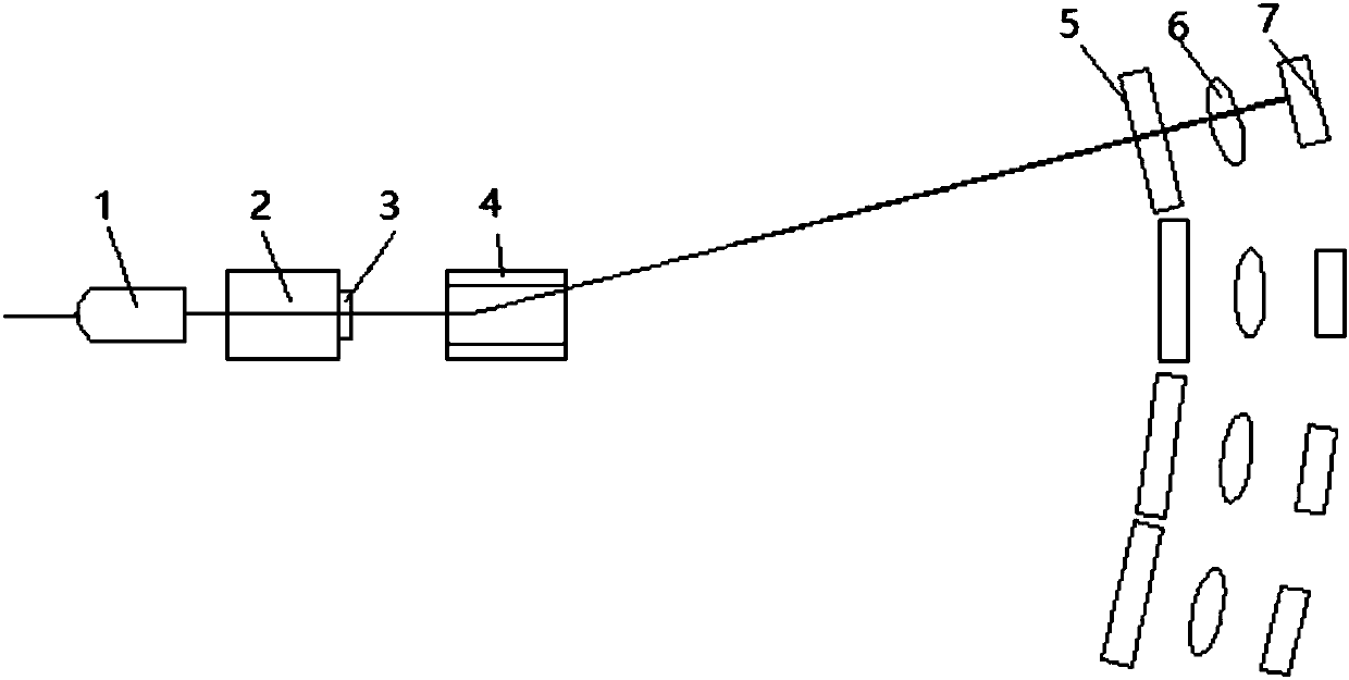
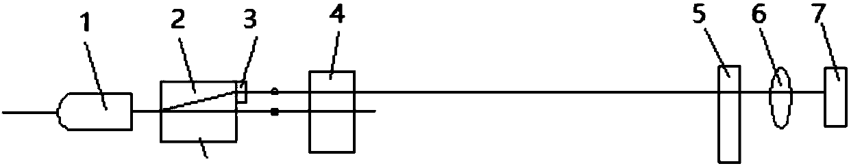
[0021] like figure 1 As shown in or 2, the present invention discloses an electro-optical scanning OSA, which includes a fiber collimator 1, a walk-off crystal 2, a first electro-optic polarizer 4, an etalon array 5, a focusing array 6 and a PD array arranged in sequence 7. The fiber collimator 1 described above is a single fiber collimator. The walk-off crystal 2 divides the light emitted by the light collimator into P polarized light and S polarized light. The exit end of the walk-off crystal 2 is provided with a broadband wave In the sheet 3 , the P-polarized light and the S-polarized light are polarized by the first electro-optic polarizer 4 , and then pass through the etalon array 5 and the focusing array 6 to arrive at the PD array 7 .

[0022] The broadband wave plate 3 is a 1 / 2 wave plate.

[0023] All etalon array 5, focusing array 6 and PD array 7 are arranged in one dimension.

[0024] The first electro-optic polarizer 4 is a KTN crystal, and electrodes are added ...

Embodiment 2

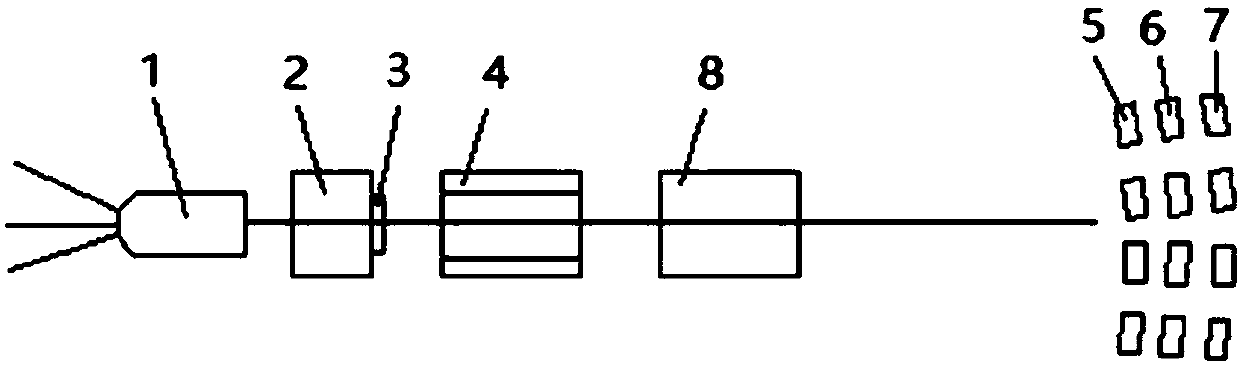
[0026] like image 3 As shown, the present invention also discloses an electro-optic scanning OSA, which includes a fiber collimator 1, a walk-off crystal 2, a first electro-optic polarizer 4, a second electro-optic polarizer 8, and an etalon array 5 arranged in sequence , focusing array 6 and PD array 7, the fiber collimator 1 is a multi-fiber collimator, the walk-off crystal 2 divides the light emitted by the light collimator into P polarized light and S polarized light, and the walk-off crystal 2 is provided with a broadband wave plate 3, the polarization directions of the first electro-optic polarizer 4 and the second electro-optic polarizer 8 are different, and the P-polarized light and S-polarized light pass through the first electro-optic polarizer 4 and the second electro-optic polarizer 8 After polarization, it passes through the etalon array 5 and the focusing array 6 to reach the PD array 7 in sequence.

[0027] The multi-fiber collimator 1 is made of single-mode o...


PUM


Abstract

The invention discloses an electro-optic scanning OSA which comprises a optical fiber collimator, a walk-off crystal, a first electro-optic polarizer, an etalon array, a focusing array and a PD array,wherein the fiber collimator, the walk-off crystal, the first electro-optic polarizer, the etalon array, the focusing array and the PD array are arranged in sequence. The optical fiber collimator isa single-optical-fiber collimator. The walk-off crystal divides light emitted by the optical fiber collimator into P-polarized light and S-polarized light. The exit end of the walk-off crystal is provided with a broadband wave plate. After the P-polarized light and the S-polarized light are polarized through the first electro-optic polarizer, the P-polarized light and the S-polarized light sequentially pass through the etalon array and the focusing array to reach the PD array. According to the invention, a one-dimensional or two-dimensional KTN is used to fabricate an electro-optical deflector, and the electro-optical deflector matches the optical fiber collimator 1 made of single-mode or multi-fiber heads of different bands, the Work-off crystal, the broadband wave plate 3, ultra-thin etalons in one-dimensional or two-dimensional arrangement and PDs in different bands to form a broadband OSA to make a fast OSA; and the electro-optic scanning OSA provided by the invention has a wider range of scan angles and can carry out rapid scanning of large scale spectra.

Description

technical field [0001] The invention relates to the field of optical fiber communication, in particular to an electro-optical scanning OSA. Background technique [0002] The existing electro-optical scanning OSA has a small scanning bandwidth and a slow scanning speed for large-scale spectra. Contents of the invention [0003] The object of the present invention is to overcome the deficiencies of the prior art and provide an OSA with electro-optical scanning. [0004] The technical scheme adopted in the present invention is: [0005] An OSA for electro-optical scanning, which includes a fiber collimator, a walk-off crystal, a first electro-optic polarizer, an etalon array, a focusing array and a PD array arranged in sequence, and the fiber collimator is a single fiber collimator, walk The -off crystal divides the light emitted by the light collimator into P-polarized light and S-polarized light. The exit end of the walk-off crystal is equipped with a broadband wave plate...

Claims


Application Information

Patent Timeline
IPC IPC(8): G02F1/29
Inventor 吴砺胡豪成林江铭李阳
Owner SHANGHAI BRANCH FUZHOU GAOYI COMM CO LTD
Why Eureka
Try Eureka