

Optical deflector and optical instrument using the same
a technology of optical instruments and deflectors, applied in the field of optical deflectors, can solve the problems of not being able to ensure a large scan angle and high scanning reproducibility at the same time, and achieve the effect of simple and easy adjustment and assured scanning reproducibility
- Summary
- Abstract
- Description
- Claims
- Application Information
AI Technical Summary
Benefits of technology
Problems solved by technology
Method used
Image

Examples
first working example
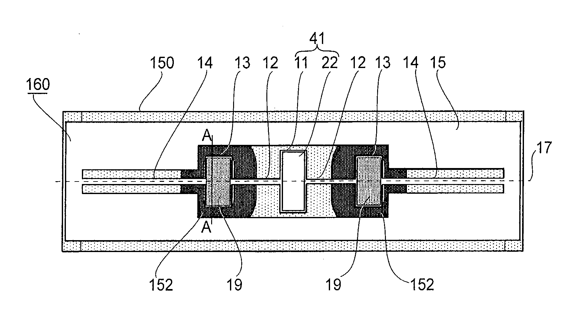
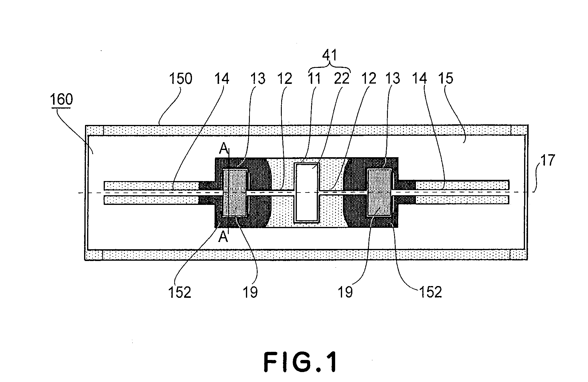
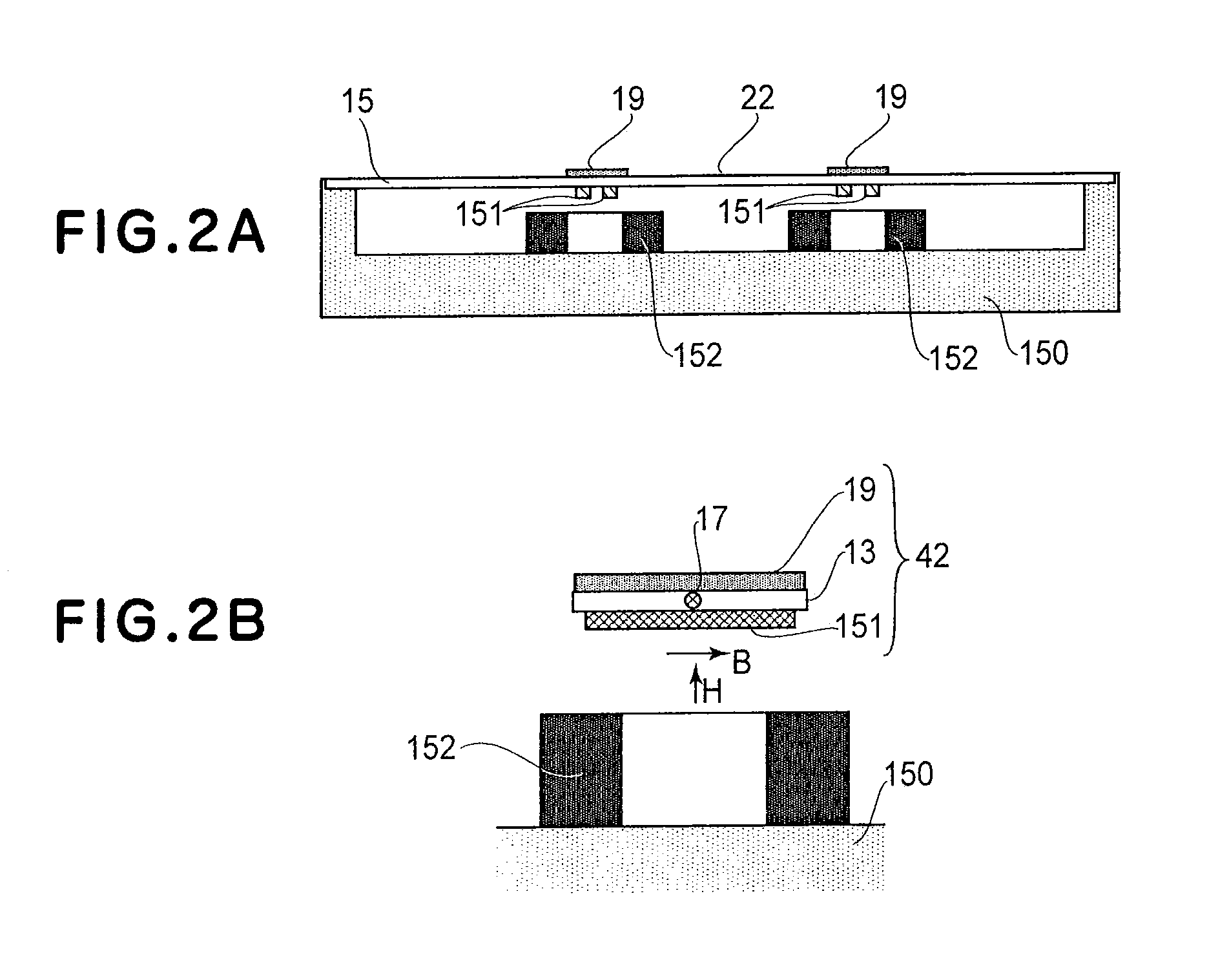
[0063]FIGS. 1, 2A, 2B and 6 show an optical deflector according to a first working example of the present invention. Here, FIG. 1 is a plan view. FIG. 2A is a sectional view taken along a plane containing an oscillation axis 17 of FIG. 1 and perpendicular to the sheet of FIG. 1. FIG. 2B is a sectional view taken along a line A-A in FIG. 1. FIG. 6 is a plan view of components of an oscillating system 160 of FIG. 1, as viewed from the bottom. The oscillating system 160 includes a reflection surface 22, a first oscillator 41, first torsion springs 12, a second oscillator 42, second torsion springs 14 and a supporting member 15.
[0064]The first oscillator 41 comprises a first movable element having a reflection surface 22 formed thereon as an optical deflecting element for deflecting light. The reflection surface 22 is made of aluminum and formed by vapor deposition. This reflection surface may be made of any other materials such as gold or copper, for example. A protection film may be f...
second working example
[0115]FIGS. 8 and 9 show an optical deflector according to a second working example of the present invention. FIG. 8 is a plan view, and FIG. 9 is a section taken along a line A-A in FIG. 8. In these drawings, the components having a similar function as those of FIG. 1 are denoted by like numerals. Hereinafter, description of those portions having a similar function as the first working example will be omitted, and only distinctive features will be explained. As shown in FIGS. 8 and 9, the optical deflector of this example comprises a first movable element 11, first torsion springs 12, second torsion springs 14, a supporting member 15, mass adjusting members 19, a reflection surface 22, a supporting member 150 and permanent magnets 151 all of which are similar to those of the first working example in respect to the material, structure and function.
[0116]The second movable element 13 of this working example is formed with cavities 30 which, as shown in FIGS. 8 and 9, extend approxima...
third working example
[0125]FIGS. 12A, 12B, 13 and 14 show an optical deflector according to a third working example of the present invention. FIG. 12A is a plane view of the side of an oscillating system 160 where a reflection surface 22 is formed, and FIG. 12B is a plan view of the opposite side of the oscillating system. FIG. 13 is a section taken along a line B-B in FIG. 12A, and FIG. 14 is a section taken along a line D-D in FIG. 12A. In these drawings, the components having a similar function as those of the first working example are denoted by like numerals. Hereinafter, description of those portions having a similar function as the first working example will be omitted, and only distinctive features will be explained. As shown in FIGS. 12A and 12B, the optical deflector of this example comprises a first movable element 11, a supporting member 15, a reflection surface 22, a supporting member 150 and permanent magnets 151 all of which are similar to those of the first working example in respect to ...
PUM
 Abstract
Description
Claims
Application Information